


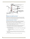
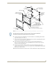
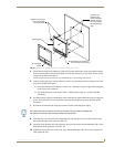


Installation Procedures: NXD-1200V Panels
46
1200V Modero Video Touch Panels
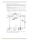
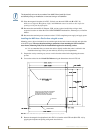
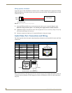
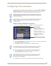
Wiring a power connection
To use the 2-pin 3.5 mm mini-Phoenix connector with a 12 VDC-compliant power supply, the incoming
PWR and GND wires from the external source must be connected to their corresponding locations on the
connector (FIG. 43).
1. Insert the PWR and GND wires on the terminal end of the 2-pin 3.5 mm mini-Phoenix cable.
Match the wiring locations of the +/- on both the power supply and the terminal connector.
2. Tighten the clamp to secure the two wires. Do not tighten the screws excessively; doing so may strip
the threads and damage the connector.
3. Verify the connection of the 2-pin 3.5 mm mini-Phoenix to the power supply.
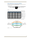
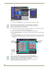
Audio/Video Port: Connections and Wiring
The following table shows the signal and pinout/pairing information used on the RJ-45 Audio and Video
connections.
Refer to the Installing CAT5 Suppression Ferrites section on page 14 for detailed information on how to
install the necessary number of CAT5 Suppression Ferrites on the Black A/V RJ-45 cable connected to
the panel.
FIG. 43 NetLinx power connector wiring diagram
Audio/Video RJ-45 Pinout Information
Pin Wire Color Function Polarity
1 Orange/White Right Audio In +
2 Orange Right Audio In -
3 Green/White Video In -
4 Blue Mic Out -
5 White/Blue Mic Out +
6 Green Video In +
7 White/Brown Left Audio In +
8 Brown Left Audio In -
PWR +
GND -
To the Touch Panel
Power Supply
TIA 568B
1 2 3 4 5 6 7 8
1 2 3 4 5 6 7 8
RJ-45 connector - pin configurations
(female) (male)