


Hardware Installation
Issue 2 November 1996
2-9
2. If the Connector cord has 25 pins:
a. Plug the remaining end into the 25-pin portion of the
M9/F25 Adapter.
b. Plug the 9-pin portion of the M9/F25 Adapter into the EIA
Connector Interface on the rear panel of the 8400B Plus Data
Module. Tighten all retaining screws.
3. If the Connector cord has 9 pins, you do not need the M9/F25 Adapter:
a. Plug the remaining end into the EIA Connector Interface on the
rear panel of the 8400B Plus Data Module. Tighten all retaining
screws.
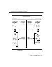
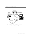
Connecting the 8400B Plus Data Module to the
PBX Wall Jack
Use the supplied DCP-type D8W telephone cord(s) to connect the 8400B Plus
Data Module to the PBX wall jack, and to the separate power supply if
necessary:
!
CAUTION:
Make certain that the AC outlet to which you connect the power
supply is unswitched (for example, not controlled by a wall switch or
light dimmer).
NOTE:
Since the 8400B Plus Data Module does not have a power on/off
switch, the unit will power on as soon as the power supply is
connected to an active AC outlet.
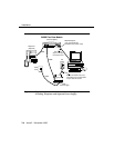
1. Insert either end of the first D8W telephone cord into the connector
labeled LINE/POWER on the rear panel of the 8400B Plus Data Module.