


125
CHAPTER 8: Modem Testing
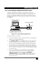
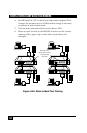
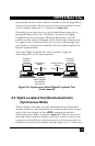
data passed from the remote modem’s transmit circuit are looped back
from the local modem and are received at the remote modem’s receive
circuit (multiple upper case “U” characters in Figure 8-6).
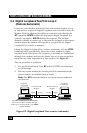
First make certain that you are set up for Synchronous operation by
placing DIP-Switch #12 in the UP position. To initiate the Digital
Loopback Test (local/manual), DIP-Switch #9 must be in the UP
position, and the Answer/Originate switch (front of the modem) must
be toggled to the UP position. Once you receive an OK message from
your modem (if responses are enabled), the local modem is placed in
Digital Loopback mode.
To exit the Digital Loopback Test (local/manual), toggle the
Answ/Orig switch to the Answer position.
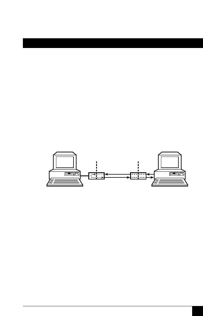
Figure 8-6. Synchronous Mode Digital Loopback Test
(local/manual)
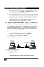
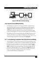
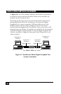
8.9 Digital Loopback Test (Remote/Automatic)
(Synchronous Mode)
This test must be run when you have a data connection with another
modem. In this test, data is passed to the remote modem and is looped
back to the local modem (as if an ATU2 command was issued in
Asynchronous test mode), as shown in Figure 8-7. This lets you test the
local and remote modem’s transmit and receive circuits, as well as your
computer’s serial COM port and the phone lines. If the test results in a
mismatch of entered/received data (multiple upper case “U” characters
UUUUU
UUUUU
Computer
or Terminal
Computer
or Terminal
Local Series II
Modem
Remote Series II
Modem
DIP switch #9
UP; Answ/Orig
switch toggled to
Answ position
when On-line
digital
analog
analog
digital