


190
SERIES II INTELLIGENT DATA/FAX MODEMS
22 RI CE 125 DCE Ring Indicator
24 XTC DA 113 DTE External Transmit Clock
25 OOS CN 142 DTE Terminal Busy
** Pin 9 need not be present in your RS232C cable
*** Pins 15 and 17 are necessary only for synchronous operation
**** Also known as DTR (Data Terminal Ready)
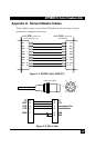
The computer or terminal should be supplied with a cable terminated
with a Cinch DB25P (or equivalent) connector mounted in a Cinch
DB51226-1 (or equivalent) hood assembly as specified by the EIA
RS232C standard.
Functional Description of RS232C Signals:
Transmitted Data - Pin 2, SD (BA)
Direction: to modem
Signals on this circuit are generated by the customer's terminal and
transferred to the transmitter of the Series II Modem. A positive signal
is a space (binary 0) and a negative signal is a mark (binary 1). The
transmitting terminal should hold this line in the marking state when
no data is being transmitted, including intervals between characters or
words. The TRANSMIT (XMT) LED indicates the status of this circuit.
Received Data - Pin 3, RD (BB)
Direction: from modem
The lead is the data output of the modem. Data signals received from
the remote modem are presented on this line. When no carrier signal is
being received (pin 8 negative), this line will be forced into a marking
condition. The RECEIVE (RCV) LED indicates the status of this signal.
Request To Send - Pin 4, RTS (CA)
Direction: to modem
The RTS signal indicates to the modem that the computer or terminal
has data that it wants to transmit.