76
SERIES II INTELLIGENT DATA/FAX MODEMS
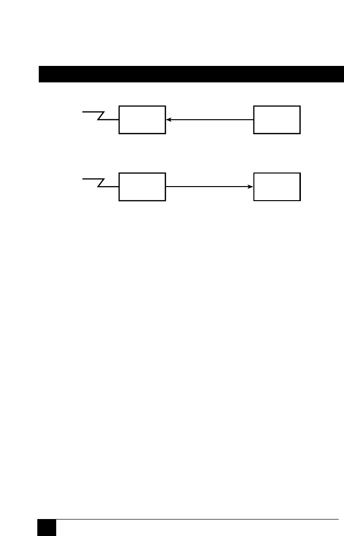
Figure 5-2. Flow Control and Pacing
Hardware Flow Control &E4
With Hardware Flow Control, the modem uses its RS232C interface to
control the flow of data from the computer or terminal to which it is
attached. The CTS (Clear to Send) signal on Pin 5 of the RS232C
interface is brought low to stop the flow of data, and is brought high
to restart it. When you select Hardware Flow Control as your Modem
Initiated Flow Control method, you will also be selecting it for Pacing.
The difference between the two, however, is that Modem-Initiated Flow
Control uses the Pin 5 CTS output signal, while Pacing uses the Pin 4
RTS input signal.
Modem commands are used to select the method of flow control used
by the Series II Modem when its error correction capabilities are used.
These commands are covered in Section 5.4.9. If neither method is
selected, the modem defaults to no flow control (&E3).
Modem
Modem
Computer or
Terminal
Computer,
Terminal, or
Printer
Modem-Initiated Flow Control
Computer-Initiated Flow Control
RS/232/V.24
data flow
data flow
RS/232/V.24


