


189
APPENDIX I: RS232C Interface Specifications
Appendix I - RS232C Interface Specifications
The Series II Modem's RS232C interface circuits have been designed to
meet the electrical specifications given in EIA (Electronic Industries
Association) RS232C standards. All signals generated by the modem are
approximately 10 volts when measured across a load of 3000 ohms or
greater. The receiving circuits of the modem will accept signals in the
3 to 25 volt range. The voltage thresholds are:
Negative = voltage more negative than –3 volts with respect to signal
ground
Positive = voltage more positive than +3 volts with respect to signal
ground
SIGNAL INFORMA
TION: NEGATIVE POSITIVE
Binary State One Zero
Signal Condition Mark Space
Control and Timing Function Off On
The input impedances of all modem circuits which accept signals from
the data processing terminal or CPU equipment have DC resistances of
4.7K. For more specific details, consult the EIA RS232C standard itself.
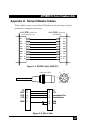
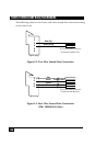
The following chart lists the EIA RS232C interface pins and circuits
present on the Series II Modem's RS232C Interface connector. All other
pins are unused.
Pin Abbrev. EIA CCITT Signal Function
No. Circuit Circuit Source
1 PG -- 101 -- Protective Ground
2 SD BA 103 DTE Transmitted Data
3 RD BB 104 DCE Received Data
4 RTS CA 105 DTE Request to Send
5 CTS CB 106 DCE Clear to Send
6 DSR CC 107 DCE Data Set Ready
7 SG AB 102 -- Signal Ground
8 CD CF 109 DCE Carrier Detect
9** +v +v -- DCE Test Voltage
12 HS -- -- DCE High Speed
15*** TC DB 114 DCE Transmit Clock
17*** RC DD 115 DCE Receive Clock
20 TR**** CD 108/2 DTE Terminal Ready