


16
SERIES II INTELLIGENT DATA/FAX MODEMS
1.7 Power
Power is supplied through an AC power transformer terminated with a
standard two-prong plug. The transformer supplies low voltage AC to
the modem, and plugs into any conventional 115 volt AC, 60 Hz, two-
prong power outlet. The power transformer supplied with the modem
is the only one that should be used. Use of any other transformer could
cause damage to the modem. A Power On/Off switch is located on the
back of the modem.
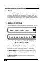
1.8 Modem LED Indicators
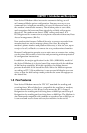
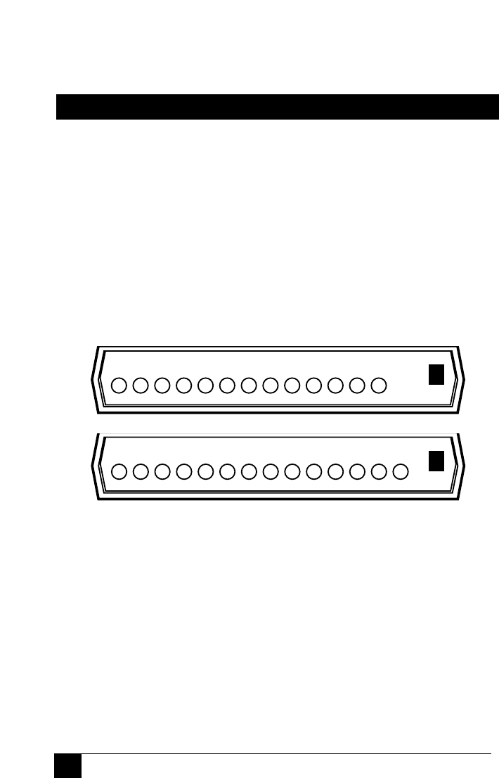
The Series II Modem has fourteen diagnostic LED indicators. They are:
Figure 1-1. LED Displays of the 336 (MD1641A, top)
and 336+ (MD1640A, bottom)
1) Transmit (Send) Data (SD). This LED blinks when data is being
transmitted, on for a space, off for a mark. The state of this LED
matches the TD circuit on Pin 2 of the RS-232C/V.24 interface.
2) Receive Data (RD). This LED blinks when data is being received,
on for a space, off for a mark. The state of this LED matches that of
the RD circuit on Pin 3 of the RS-232C/V.24 interface.
3) Carrier Detect (CD). This LED is lit when a valid carrier tone
has been detected.
SD
Send
RD
Rcv
CD
Carr
33.6
33.6K
24.0
24.0K
19.2
19.2K
14.4
14.4K
96
9600
24
2400
OH
Off Hk
TR
Rdy
EC
V.42
FX
Fax
ERR
Error
Answ
Orig
Voice/
Data
SD
Send
RD
Rcv
CD
Carr
33.6
33.6K
24.0
24.0K
19.2
19.2K
14.4
14.4K
96
9600
24
2400
OH
Off Hk
TR
Rdy
EC
V.42
FX
Fax
Answ
Orig
Voice/
Data