


CHAPTER 4 DISASSEMBLY AND RE-ASSEMBLY
4-29
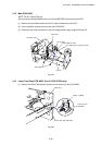
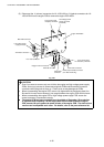
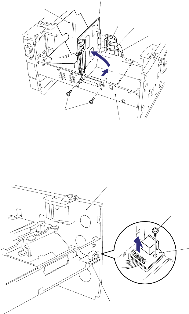
3.12 Main PCB ASSY
NOTE: For HL-1250/1270N only
Ensure that any installed SIMM memory is removed BEFORE removing the main PCB.
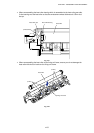
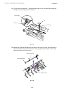
(1) Remove the two M3x8 screws from the I/F plate to release the main PCB.
(2) Lift the insulation sheet and remove the main PCB ASSY.
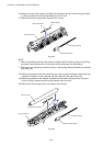
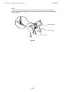
(3) Disconnect the three connectors for the low-voltage power supply, engine PCB and LD.
Fig. 4-51
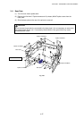
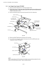
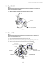
3.13 Lower Tray Relay PCB ASSY (for HL-1250/1270N only)
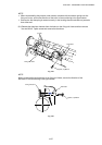
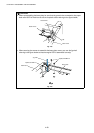
(1) Remove the M3x6 Taptite screw and remove the lower tray relay PCB ASSY.
Fig. 4-52
Taptite, cup M3x6
Lower tray relay
PCB ASSY
Lower tray relay PCB ASSY
Main frame
Screw M3x8
Insulation sheet
Main PCB
Low-voltage power supply connector
Engine PCB connector
LD connector
I/F plate
➀
➁