


CHAPTER 4 DISASSEMBLY AND RE-ASSEMBLY
4-30
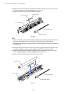
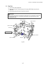
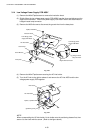
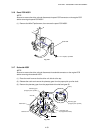
3.14 Low-Voltage Power Supply PCB ASSY
(1) Remove the M3x8 Taptite screw to remove the insulation sheet.
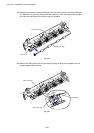
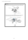
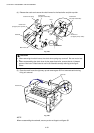
(2) Slightly lift up the low-voltage power supply PCB ASSY from the frame and disconnect the
engine PCB connector. Then lift the power supply PCB ASSY further and disconnect the
halogen heater lamp connector.
(3) Remove the M3.5x6 screw to disconnect the ground wire from the base plate.
Fig. 4-53
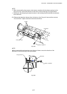
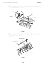
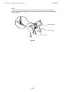
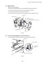
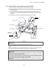
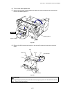
(4) Remove the M3x6 Taptite screw securing the AC inlet holder.
(5) Turn the AC inlet to the right to release it and remove the AC inlet ASSY and the low-
voltage power supply PCB together.
Fig. 4-54
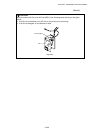
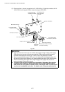
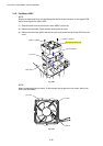
NOTE:
When re-assembling the AC inlet holder, fix the holder onto the positioning bosses first, then
secure it to the frame with the screw. (Refer to the figure above.)
Taptite, bind M3x8
AC inlet holder
Low-voltage power
supply PCB ASSY
Ground wire
Screw M3.5x6
Halogen heater
lamp connector
Engine PCB connector
Low-voltage power
supply PCB ASSY
Base plate
Taptite, cup M3x6
AC inlet holder
Main frame
(positioning boss)
Insulation sheet
Step (2)