


CHAPTER 3 THEORY OF OPERATION
3-18
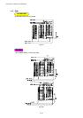
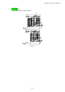
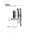
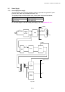
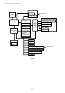
1.4 Engine PCB
The gate array which transforms the serial signal from the main PCB into the parallel signal is
mounted on the engine PCB.
The engine PCB controls the following parts by using the transferred signal data;
•
Main motor
•
Toner sensor
•
Panel PCB
•
Cover sensor
•
Fan motor
•
Front registration sensor
•
Thermistor
•
Rear registration sensor
•
Polygon motor
•
Upper paper cassette sensor (HL-1250/1270N only)
•
Solenoid
•
Lower paper cassette registration sensor (HL-1250/1270N only)
•
High-voltage power supply
For the circuit diagram of the engine PCB, see Appendix 18.
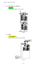
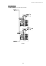
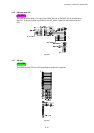
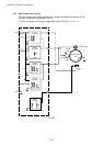
1.5 BR-net PCB (for HL-1270N only)
The BR-net PCB is connected to the ASIC mounted on the main PCB through the PCI bus.
The Ethernet controller, AM79C973AKC is mounted on the BR-net PCB. The controller
incorporates the 10/100 Mbps physical interface which conforms to IEEE 802.3 and is
connected with the external Ethernet through the RJ-45 connector.
For the circuit diagram of the BR-net PCB, see Appendix 19.