


CHAPTER 3 THEORY OF OPERATION
3-4
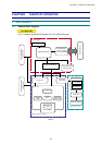
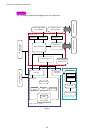
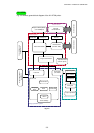
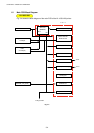
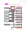
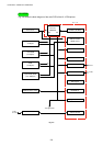
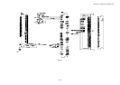
1.2 Main PCB Block Diagram
Fig. 3-4 shows the block diagram of the main PCB of the HL-1030/1240 printer.
Reset Circuit
Program + Font ROM
1.0 Mbytes
RAM
(2.0 Mbytes)
EEPROM (128 8 bits)
A S I C
Oscillator (32.7MHz)
Address Decoder
DRAM Control
Timer
FIFO
CDCC Parallel I/O
Soft Support
EEPROM I/O
Engine Control I/O
To Engine PCB
CPU Core
(MB86833)
BUS
INT
To PC
USB I/O (HL-1240 only)
To PC
Fig. 3-4
HL-1030/1240