


CHAPTER 4 DISASSEMBLY AND RE-ASSEMBLY
4-18
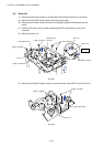
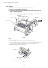
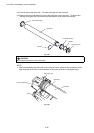
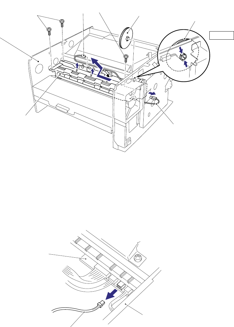
3.10 Fixing Unit
(1) Place the main frame on its base so that the rear side is facing you.
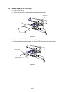
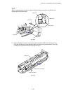
(2) Press the two hooks inwards to remove gear 59.
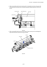
(3) Disconnect the two connectors of the heater harness and release the harness from the
hooks on the top of the fixing unit.
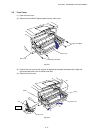
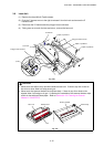
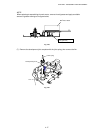
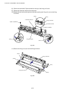
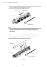
(4) Remove the one M3x8 Taptite screw and two shoulder screws securing the fixing unit,
taking care not to lose the contact spring fitted to the front left hand.
Fig. 4-31
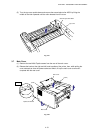
NOTE:
When re-assembling the fixing unit, ensure you do not forget to refit gear 59.
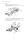
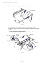
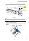
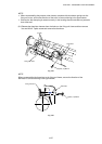
(5) Lift up the fixing unit and move it toward you and to the left to allow the drive gear to clear
the frame and then disconnect the thermistor connector from the engine PCB.
(6) Remove the fixing unit from the main frame.
Fig. 4-32
Shoulder screw
Thermistor connector
Main frame
Engine PCB
Heater harness
connector
Main frame
Heater harness
G
ear 59
Gear 59
Fixing unit
Taptite, cup M3x8
Step (2)