


CHAPTER 4 DISASSEMBLY AND RE-ASSEMBLY
4-21
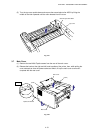
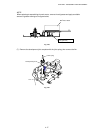
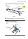
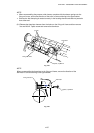
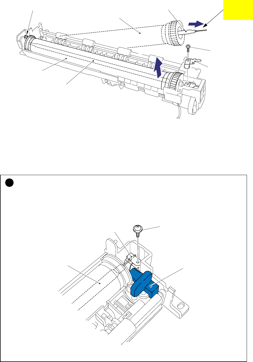
(12) Remove the one M3x10 Taptite screw securing the halogen lamp connector plate at the
drive unit side of the fixing unit frame and then loosen the M3x6 screw at the other side.
(13) Lift the right hand end of the heat roller and remove the halogen heater lamp from the heat
roller.
Fig. 4-37
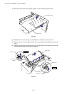
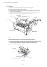
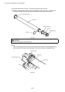
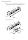
NOTE:
When re-assembling the halogen heater lamp, ensure that the direction of the halogen heater
lamp is correct referring to the figure above.
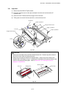
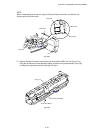
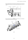
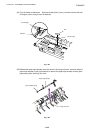
!
CAUTION:
•
Never touch the surface of the halogen heater lamp.
•
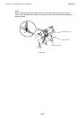
When securing the screw to assemble the halogen lamp connector plate, ensure you use
the plastic jig as shown in the figure below to avoid damaging the edge of the halogen
heater lamp.
Fig. 4-38
Halogen heater lamp
Heat roller
Taptite, pan M3x10
Screw, cup M3x6
Halogen heater lamp
Heat roller
Colored side
115V: Yellow
230V: Purple
Halogen lamp
connector plate
Taptite, pan M3x10
Halogen lamp
connector plate
Plastic jig
Halogen heater lamp