


CHAPTER 4 DISASSEMBLY AND RE-ASSEMBLY
4-32
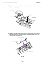
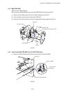
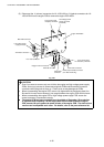
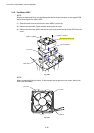
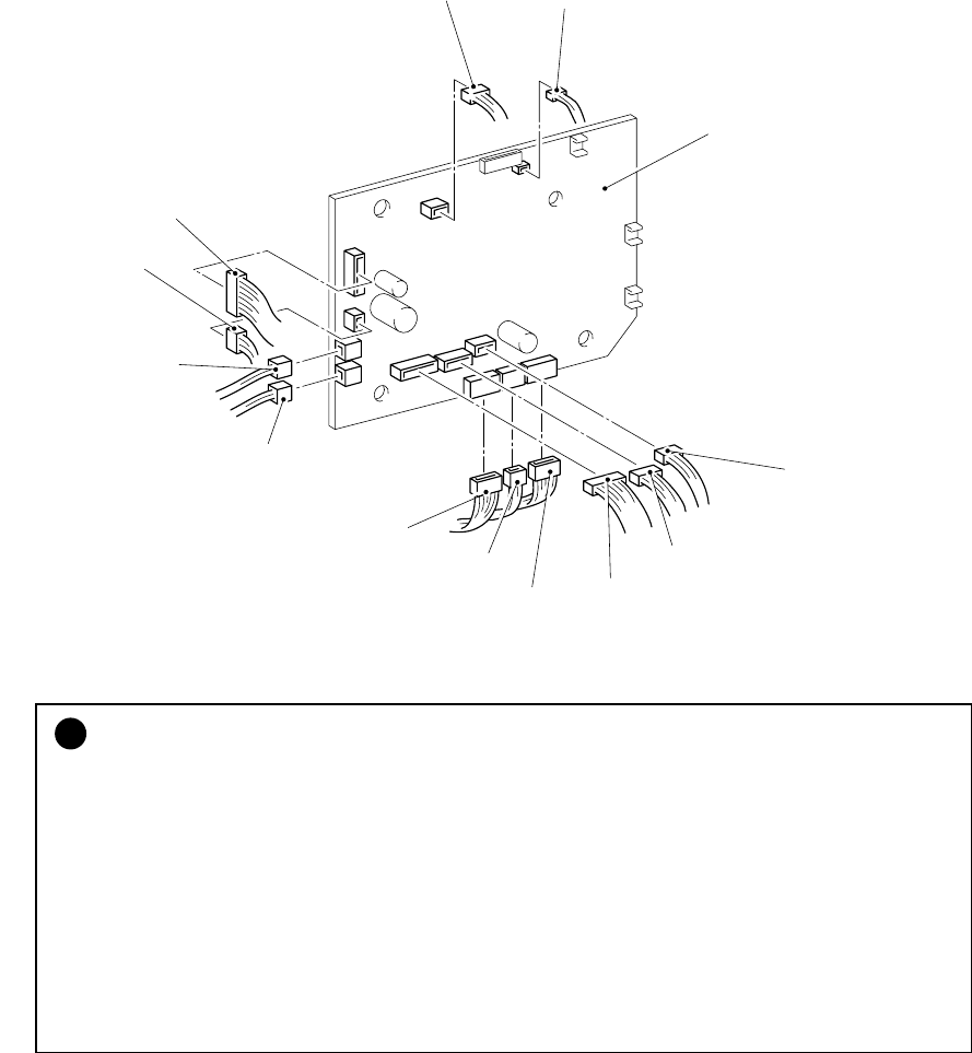
(5) Disconnect the 11 (eleven) connectors for HL-1030/1240 or 12 (twelve) connectors for HL-
1250/1270N from the engine PCB to remove the engine PCB ASSY.
Fig. 4-56
!
CAUTION:
•
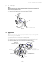
Even if you want to remove only one of either the engine and high-voltage power supply
PCBs, ensure you remove all screws securing both PCBs and disconnect the central
connector while lifting both of them up. Failure to do so may damage the PCBs.
•
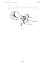
When re-assembling the engine PCB, ensure it is aligned with the positioning boss first.
Be careful the main motor harness is not caught between the engine PCB and the frame.
•
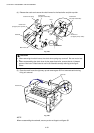
When re-assembling the engine PCB or high-voltage power supply PCB, ensure the
central connector is connected correctly.
•
• •
•
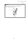
The engine PCB has been upgraded from the middle of September ’99 production
to improve the print quality. As we supply both old and new versions of engine
PCB, ensure that you replace the same version of the engine PCB. The old and new
versions are incompatible each other. For details, refer to the parts reference list.
Main PCB connector
Toner sensor (light
emission) connector
Fan motor connector
Thermistor connector
Low-voltage power
supply connector
Polygon motor connector
Panel PCB
connector
Lower paper cassette connector
(HL-1250/1270N only)
Main motor connector
Solenoid connector
Engine PCB ASSY
Low-voltage power
supply connector
(for HVPS)
Toner sensor (light
reception) connector