


CHAPTER 4 DISASSEMBLY AND RE-ASSEMBLY
4-31
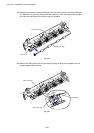
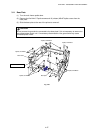
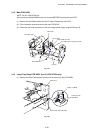
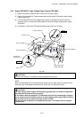
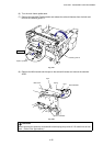
3.15 Engine PCB ASSY / High-Voltage Power Supply PCB ASSY
(1) Remove the M4x12 Taptite screw to remove the insulation sheet.
(2) Remove the three M4x12 Taptite screws securing the engine PCB and the high-voltage
power supply PCB.
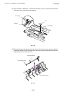
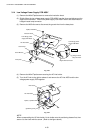
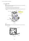
(3) Lift the engine PCB and high-voltage power supply PCB together and disconnect the
connector which connects two PCBs together to remove the high-voltage power supply
PCB ASSY.
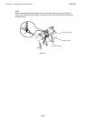
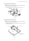
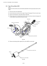
(4) If necessary, remove the T/R electrode helical spring from the T/R plate.
Fig. 4-55
!
CAUTION:
Be sure not to lose the T/R electrode helical spring after removing it.
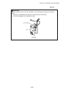
NOTE:
When re-assembling the T/R electrode helical spring onto the plate, press the spring onto the
plate firmly with a flat bladed screwdriver and ensure that it is retained securely.
!
CAUTION:
The high-voltage power supply PCB has been upgraded from the middle of September
’99 production to improve the print quality.
In accordance with the change the T/R electrode helical spring has been also changed.
As we supply both old and new versions of high-voltage power supply PCB and helical
spring, ensure that you replace the same version of them.
The old and new versions are incompatible each other. For details, refer to the parts
reference list.
Screw, bind M4x12
Screw, bind M4x12
Engine PCB ASSY
High-voltage power
supply PCB ASSY
T/R electrode
helical spring
Chute
Insulation sheet
Screw, bind M4x10
Step (4)
Step (3)