


CHAPTER 4 DISASSEMBLY AND RE-ASSEMBLY
4-20
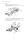
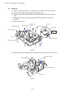
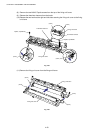
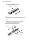
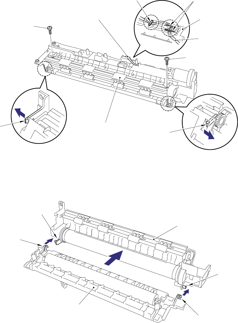
(8) Remove the two M3x20 Taptite screws from the top of the fixing unit frame.
(9) Release the thermistor harness from the hooks.
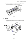
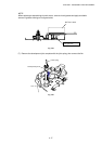
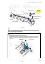
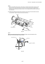
(10) Release the two hooks at the right and left sides securing the fixing unit cover to the fixing
unit frame.
Fig. 4-35
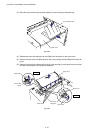
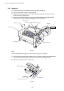
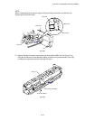
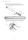
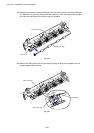
(11) Remove the fixing unit cover from the fixing unit frame.
Fig. 4-36
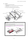
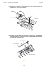
Fixing unit frame
Fixing unit cover
(hook)
(hook)
(hook)
(hook)
Fixing unit frame
(hook)
Thermistor harness
(hook)
Taptite, cup M3x20
Thermistor harness
Taptite, cup M3x20
Fixing unit frame
(hook)
(hook)