


Appendix A The External Optical Bypass Module
The External Optical Bypass Module Front Panel
Cisco SCE 1000 2xGBE Installation and Configuration Guide
OL-7821-05 A-3
The External Optical Bypass Module Front Panel
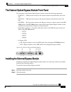
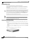
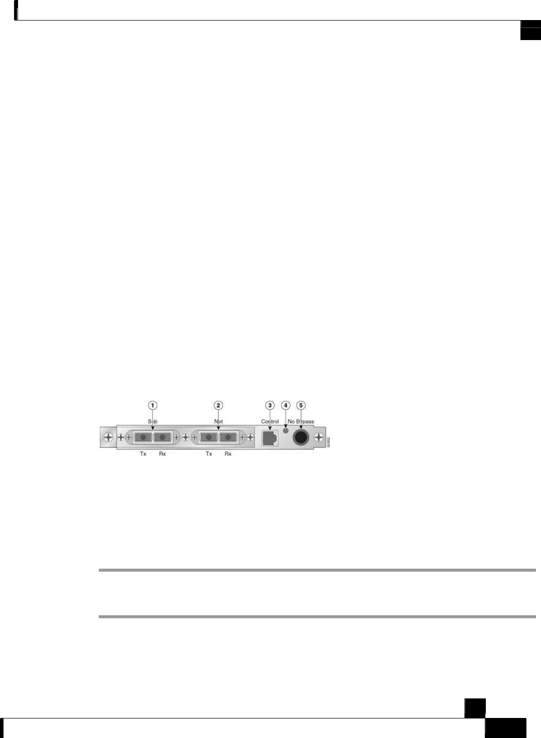
The front panel of the External Optical bypass module contains the following components:
• SUB Rx/Tx — GBE port that connects to the network element on the Subscriber side of the
link.
• NET Rx/Tx — GBE port that connects to the network element on the Network side of the
link.
• CONTROL — RJ-45 port that connects to the Bypass connector on the rear panel of the SCE
1000 platform. The SCE 1000 platform controls the External Optical Bypass module via this
connection, by the presence or absence of electrical power.
• Pigtail fiber connectors — Four fiber cables that connect to the GBE link ports on the front
panel of the SCE 1000 platform
• NET Tx
• NET Rx
• SUB Tx
• SUB Rx
• No Bypass LED:
• ON = Bypass module is not active (GBE traffic flows through the SCE 1000 platform)
• OFF = Bypass module is active (GBE traffic flows through the bypass module)
Figure
A-3: External Optical Bypass Module
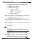
Installing the External Bypass Module
Installation of the External Optical Bypass module requires two main steps, which are described
in detail in the following sections.
To install the External Optical Bypass module:
Step 1 Install the module in the rack.
Step 2 Cable the module.