


Chapter 6 Cabling the Line Ports and Completing the Installation
Connecting the line ports to the network
Cisco SCE 1000 2xGBE Installation and Configuration Guide
OL-7821-05 6-5
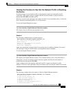
Step 1 To enter the Global Configuration Mode, at the SCE 1000# prompt, type configure and press
Enter.
The SCE 1000(config)# prompt appears.
Step 2 To enter the desired GBE port interface, type interface GigabitEthernet 0/portnumber, and
press Enter, where portnumber is the number of the selected port (1 or 2).
The SCE 1000(config if)# prompt appears.
Step 3 Type auto-negotiate and press Enter.
The SCE 1000(config if)# prompt appears.
Step 4 To return to Global Configuration Mode, type exit and press Enter.
The SCE 1000(config)# prompt appears.
Repeat this procedure to configure auto-negotiation for the other GBE port interfaces as needed.
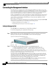
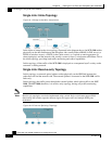
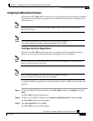
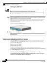
Connecting the GBE Line Interface Ports
The following sections present the general procedure for cabling the GBE interface ports. Refer to
Cabling Diagrams (on page 6-1) to find the appropriate cabling diagram for the topology of your
system for the specific connections required.
Note
When installing an External Optical Bypass module, the SCE 1000 line ports are connected to the
module. See Cabling the External Optical Bypass Module (on page A-4) for complete instructions.
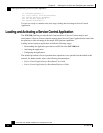
Fiber Specifications
The following table presents the fiber specifications. The SCE 1000 may be ordered with either
Multimode or Single Mode transceivers The transceiver type is indicated on the front panel under
the ports. Note that both transceivers on any individual SCE 1000 are the same, either 850nm
Multimode OR 1310nm Single Mode.
Table 6-1 Fiber Specifications
SCE Model Transceiver Transmit Power Receive Power Typical (Max.) Distance
SCE 1000 2xGBE
MM
850nm Multimode –9.5 to –4 dBm –17 to 0 dBm
• 750m for 50µm Core
Diameter MMF
• 400m for 62.5µm Core
Diameter MMF
SCE 1000 2xGBE
SM
1310nm FRP laser
Single Mode
–9.5 to –3 dBm –20 to 3 dBm 10 km for 9.0µm Core
Diameter SMF