


Chapter 4 Installation and Maintenance
Fan Module Overview
Cisco SCE 1000 2xGBE Installation and Configuration Guide
4-20 OL-7821-05
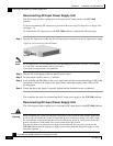
Step 8 Ensure that the power supply is properly aligned and the installation screw is tightened.
This completes the steps for reconnecting the DC-input power supply to the SCE 1000 platform.
Fan Module Overview
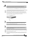
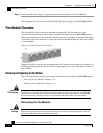
The fan module provides cooling for the internal components. The fan drawer is a field-
replaceable unit containing five fans, and is installed at the right rear of the SCE 1000 platform.
When a fan malfunctions, the fan module should be replaced as promptly as possible. Although it
is possible for the unit to function for some time with one non-functioning fan, this is not optimal
or recommended.
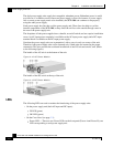
Figure
4-16: SCE Platform Fan Module
When a fan failure occurs, the environment monitor will send an error message to the console. An
SNMP trap indicating that the fan is not functioning properly is also sent. Note that a fan failure is
often audible.
Removing and Replacing the Fan Module
The following sections explain how to remove and replace a fan module in a SCE 1000 platform:
• Removing the Fan Module (on page 4-20)
• Replacing the Fan Module (on page 4-21)
ESD Warning
Do not remove or install modules without using appropriate anti-static guard measures. The SCE 1000
includes an anti-static wrist strap in the accessory kit. Attach the copper tape strap to an unpainted metal
surface on the chassis. You may leave the strap connected to the chassis when your have finished.
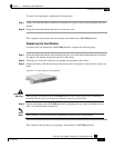
Removing the Fan Module
Warning
When removing the fan drawer, keep hands and fingers away from the spinning fan blades. Let the fan
blades stop completely before removing the fan drawer.