


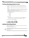

Appendix A The External Optical Bypass Module
Installing the External Bypass Module
Cisco SCE 1000 2xGBE Installation and Configuration Guide
A-4 OL-7821-05
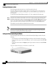
Installing the Module in a Rack
The following procedure describes how to install the module in the rack.
Note that, although each module is shipped with its own mounting panel, it is not necessary to
install each module in a separate mounting panel. Up to three modules may be installed in one
mounting panel.
To install the External Optical Bypass module in a 19" rack, complete the following steps:
Step 1 Using the screws attached to the module, screw it into an empty position in the mounting panel.
Step 2 Secure the module panel to the two front posts of the rack above the SCE 1000 platform. Leave at
least 1.5 cm vertical clearance between the SCE 1000 platform and the module panel to provide
space for the cables from the front panel of the module to the rear of the SCE 1000 platform.
The module can now be cabled as explained in the next section.
Note
If only one or two External Optical Bypass modules are deployed in one panel, the empty third position
can be used for transferring the cables, thus saving rack space.
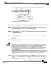
Cabling the External Optical Bypass Module
The following procedure describes how to cable the External Optical Bypass module. Note the
following:
• All connections to the External Optical Bypass module are on the front panel of the module.
• Connect the fiber (steps 3 and 4) to the GBE ports 1 and 2 on the front panel of the SCE 1000
platform.
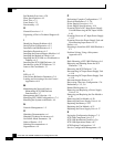
• Connect the control cable to the Bypass 9-pin D-Type connector on the rear of the SCE 1000
platform.
Figure
A-4: Bypass Connector on the Rear of the SCE 1000