


Cisco SCE 1000 2xGBE Installation and Configuration Guide
OL-7821-05 6-1
This chapter provides instructions for cabling the Gigabit Ethernet ports and for configuring
Gigabit Ethernet (GBE) interface parameters.
Note
When installing an External Optical Bypass module, the SCE 1000 line ports are connected to the
module. See Cabling the External Optical Bypass Module (on page A-4) for complete instructions.
This chapter contains the following sections:
• Connecting the line ports to the network 6-1
• Loading and Activating a Service Control Application 6-8
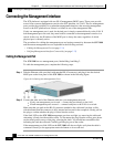
Connecting the line ports to the network
The procedures for cabling the line ports, configuring the interface parameters, and testing
connectivity of the links are explained in the following sections:
• Cabling Diagrams (on page 6-1)
• Configuring the GBE Interface Parameters (on page 6-3)
• Connecting the GBE Line Interface Ports (on page 6-5)
• Testing Connectivity: Examining Link LEDs, GBE Counters (on page 6-6)
Cabling Diagrams
Before beginning, find the appropriate cabling diagram for the topology in your installation:
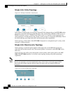
• Single SCE 1000 topologies
• Single Link: Inline Topology (on page 6-2)
• Single Link: Receive-only Topology (on page 6-2)
CHAPTER 6
Cabling the Line Ports and Completing the
Installation