


Chapter 2 Introduction to the SCE Platform
Front Panel
Cisco SCE 1000 2xGBE Installation and Configuration Guide
2-2 OL-7821-05
Front Panel
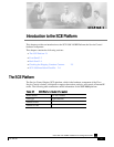
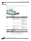
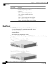
The SCE 1000 Front Panel consists of ports and LEDs as shown in the following figures and
tables.
Figure
2-1: SCE Platform Front Panel
Table
2-2 SCE 1000
Ports
Port Quantity Description Connect This Port To…
Mng1/
Mng2
2 10/100/1000 Ethernet RJ-45 ports for
management of the SCE 1000.
CLI designation: interface Management
0/1, 0/2.
A LAN using an FE cable
with an RJ-45 connector.
If both interfaces are used to
provide a redundant
management interface,
connect both ports to the LAN
via a switch.
Console 1 RS-232 RJ-45 port for use by technicians A local terminal (console)
using an RS-232 cable with
an RJ-45 connector, as
provided in the SCE 1000 kit.
AUX 1 RS-232 RJ-45 port used by technicians
GBE ports 1
and 2
2 GigabitEthernet ports for connecting to
the link.
CLI designation: interface
GigabitEthernet 0/1 and 0/2
Refer to Connecting the Line
Ports (on page 6-1) for
cabling diagrams for various
topologies
Table
2-3 SCE 1000
LED Groups
LED Groups Description
Power A
• Continuous green — Power supply A is functioning normally
• Red — Power supply A present, but malfunctioning
• Unlit — Power supply A is either not present or has failed.