


Chapter 4 Installation and Maintenance
Fan Module Overview
Cisco SCE 1000 2xGBE Installation and Configuration Guide
OL-7821-05 4-21
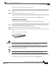
To remove the fan module, complete the following steps:
Step 1 Using a 1/4-inch flat-blade screwdriver, loosen the two captive screws on the faceplate of the fan
module.
Step 2 Grasp the fan module handle and remove it from the router.
This completes the procedure for removing the fan module from a SCE 1000 platform.
Replacing the Fan Module
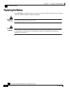
To install a new fan module into a SCE 1000 platform, complete the following steps:
Step 1 Grasp the fan module handle with one hand and place your other hand underneath the fan module
for support. The handle of the unit should be at the bottom.
Step 2 Fit the groove in the side of the new fan module into the guide in the chassis.
Step 3 Gently, but firmly, slide the module into the chassis until its faceplate is flush with the chassis rear
panel.
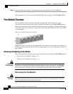
Figure
4-17: Inserting the Fan Module
Warning
When inserting a fan module into the SCE 1000 platform, do not use unnecessary force; slamming the
fan module into the chassis can damage the connectors on the rear of the module.
Step 4 Seat the fan module in the SCE 1000 platform by tightening the two captive installation screws
with a 1/4-inch flat-blade screwdriver.
Note
The fan module is not fully seated until you tighten the installation screws on the faceplate.
This completes the procedures for replacing a fan module in a SCE 1000 platform.