


Chapter 6 Cabling the Line Ports and Completing the Installation
Connecting the line ports to the network
Cisco SCE 1000 2xGBE Installation and Configuration Guide
6-6 OL-7821-05
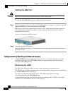
Cabling the GBE Port
Warning
Class 1 laser. Avoid exposure to radiation and do not stare into open aperture.
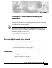
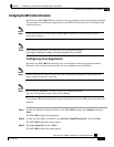
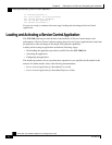
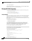
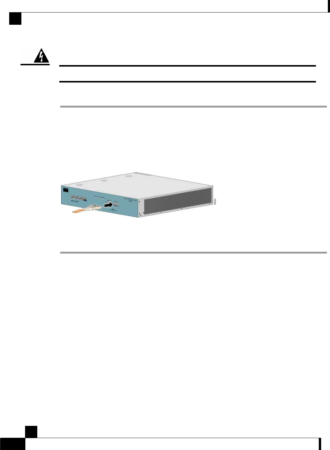
To cable the SCE 1000 GBE line port, complete the following steps:
Step 1 Take the appropriate fiber optic cable (see Fiber Specifications (on page 6-5)) and plug it into the
appropriate GBE port on the front panel of the SCE 1000.
Make sure to push on the connector until you hear a click, which indicates that the connector is
fully inserted and secured in the receptacle. Always make sure that you insert the connector
completely into the socket.
Figure
6-3: Cabling the GBE Interface
Step 2 Verify that the link LED is green.
If the link LED does not light, try removing the network cable plug and reinserting it firmly into
the module socket.
Testing Connectivity: Examining Link LEDs and Counters
If the SCE 1000 platform has been powered up, test now to verify that connectivity has been
established on all links. If the SCE 1000 platform is not powered up, perform this step after
starting the SCE 1000 platform.
Examining the LEDs
The GBE Link LED must be green in order to verify that an active connection exists.
The GBE Rx and Tx LEDs (if flashing green) indicate that traffic is being received or transmitted
by the SCE 1000 platform, respectively.
Note that in an inline topology, the Rx and Tx LEDs indicate that packets are being
received/transmitted by the SCE 1000 platform.
In optical splitter topologies, the Rx LEDs are the sole indicators. The Tx LEDs do not “blink”,
since the Tx is not connected to the port in this topology.