


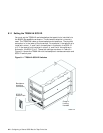

Use the following steps to install an ATMworks adapter. See the ATMworks
350 Adapter Installation and Service guide for more information. Be sure
to use the antistatic ground strap.
1. Remove the adapter extender bracket if the ATMworks 350 is to be
installed in an AlphaServer 2100 system.
2. Remove the option slot cover from the appropriate PCI or
TURBOchannel slot.
3. Install the adapter module.
4. Install the multimode fiber optics (SC connectors) cables as follows:
• Remove the optical dust caps.
• Line up the transmit cable connector with the transmit port and
the receive cable connector with the receive port and insert the SC
connectors. The ATMworks transmit port is identified by an arrow
exiting a circle. The receive port is identified by an arrow entering a
circle.
Listen for the click indicating that the connector is properly seated.
___________________ Note ___________________
Ensure that the bend radius of any fiber optic cable
exceeds 2.5 cm (1 inch) to prevent breaking the glass.
When removing an SC connector, do not pull on the cable.
Pull on the cable connector only.
To verify that the cables are connected correctly, see Section 7.3.
7.3 Verifying ATM Fiber Optic Cable Connectivity
The fiber optic cables from some suppliers are not labeled or color coded,
and as the system and ATM switch may be separated by a great distance,
verifying that the cables are connected correctly may be difficult.
The ATMworks adapters start sending idle cells when the ATM driver is
enabled. The adapter sends idle cells even when no data is being sent. ATM
switches provide an indication that they are receiving the idle cells.
To verify that the fiber optic cables are properly connected, follow these steps:
1. Verify that both the transmit and receive connectors are seated properly
at both the ATM adapter and the ATM switch.
2. Verify that the following ATM subsets have been installed with this
command:
7–4 Preparing ATM Adapters