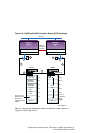
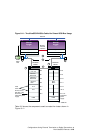
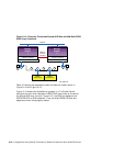
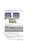
To prepare two UltraSCSI BA356 storage shelves for shared SCSI bus usage,
(see Figure 9–11) follow these steps:
1. Complete the steps of Section 9.4.1.3 for each UltraSCSI BA356. Ensure
that the personality module address switches on one UltraSCSI BA356
are set to select SCSI IDs 0 through 6 and the address switches on
the other UltraSCSI BA356 personality module are set to select SCSI
IDs 8 through 14.
2. You will need two H8861-AA VHDCI trilink connectors. If either of
the UltraSCSI BA356 storage shelves will be on the end of the SCSI
bus, attach an a H8863-AA terminator to one of the H8861-AA trilink
connectors. Install the trilink with the terminator on connector JA1 of
the DS-BA35X-DA personality module of the UltraSCSI BA356 that will
be on the end of the SCSI bus. Install the other H8861-AA trilink on JA1
of the DS-BA35X-DA personality module of the other UltraSCSI BA356.
3. Connect a BN37A VHDCI to VHDCI cable between the H8861-AA
trilink connectors on the UltraSCSI BA356s.
4. When the KZPSA-BBs or KZPBA-CBs are installed:
• If one of the UltraSCSI BA356s is on the end of the SCSI bus,
install a BN38C (or BN38D) HD68 to VHDCI cable between one of
the BN21W-0B Y cables (on the host bus adapters) and the open
connector on the H8861-AA trilink connector on the DS-BA35X-DA
personality module. Connect the BN21W-0B Y cables on the two
member system host adapters together with a BN21K (or BN21L)
cable.
• If the UltraSCSI BA356s are in the middle of the SCSI bus, install a
BN38C (or BN38D) HD68 to VHDCI cable between the BN21W-0B
Y cable on each host bus adapter and the open connector on the
H8861-AA trilink connector on the DS-BA35X-DA personality
modules.
9–22 Configurations Using External Termination or Radial Connections to Non-UltraSCSI Devices


