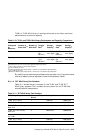
8.10.6 Connecting the TL893 and TL896 Automated Tape Libraries to
the Shared SCSI Bus
The TL893 and TL896 Automated Tape Libraries (ATLs) have up to 3
meters of internal SCSI cabling on each SCSI bus. Because of the internal
SCSI cable lengths, it is not possible to use a trilink connector or Y cable to
terminate the SCSI bus external to the library as is done with other devices
on the shared SCSI bus. Each SCSI bus must be terminated internal to the
tape library at the tape drive itself with the installed SCSI terminators.
Therefore, TL893 and TL896 tape libraries must be on the end of the shared
SCSI bus.
In a TruCluster Server cluster with TL893 or TL896 tape libraries, the
member systems and StorageWorks enclosures or RAID subsystems may
be isolated from the shared SCSI bus because they use trilink connectors
or Y cables. However, if there is disk storage and an ATL on the same
shared SCSI bus, the ASE must be shut down to remove a tape library from
the shared bus.
You can reconfigure the tape drives and robotics controller to generate other
bus configurations by using the jumper cable (ATL part number 0425017)
supplied in the accessories kit shipped with each TL893 or TL896 unit.
Remove the terminator from one drive and remove the internal SCSI cable
from the other drive to be daisy chained. Use the jumper cable to connect the
two drives and place them on the same SCSI bus.
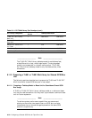
______________________ Note _______________________
We recommend that you not place more than two drives on any
one SCSI bus in these tape libraries.
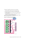
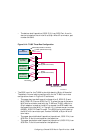
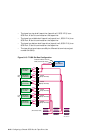
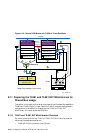
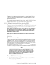
Figure 8–16 shows a sample TruCluster Server cluster using a TL896 tape
library in a three-bus configuration. In this configuration, tape drive 4 (Port
E) has been jumpered to tape drive 5, tape drive 2 (Port A) has been jumpered
to tape drive 3, and tape drive 1 (Port B) has been jumpered to tape drive 0.
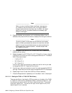
To add a TL893 or TL896 tape library to a shared SCSI bus, select the
member system that will be the next to the last device on the shared SCSI
bus (the tape library always has to be the last device on the shared SCSI
bus). Connect a BN21K, BN21L, or BN31G cable between the Y cable on
the SCSI bus controller on that member system and the appropriate tape
library port. In Figure 8–16, one shared SCSI bus is connected to port
B (tape drives 0 and 1), one shared SCSI bus is connected to port A (tape
drives 2 and 3), and a third shared SCSI bus is connected to port E (tape
drives 4 and 5 and the MUC).
Configuring a Shared SCSI Bus for Tape Drive Use 8–47


