


on adding additional cabinets. Up to five cabinets are supported with the
TruCluster Server.
For TruCluster Server, the tape cartridges in all the cabinets are combined
into one logical unit, with consecutive numbering from the first cabinet to
the last cabinet, by an upgrade from the multi-unit, multi-LUN (MUML)
configuration to a multi-unit, single-LUN (MUSL) configuration. See
the
TL82X/TL89X MUML to MUSL Upgrade Instructions manual for
information on the firmware upgrade.
These tape libraries each have a multi-unit controller (MUC) that serves
two functions:
• It is a SCSI adapter that allows the SCSI interface to control
communications between the host and the tape library.
• It permits the host to control up to five attached library units in a
multi-unit configuration. Multi-unit configurations are not discussed in
this manual. For more information on multi-unit configurations, see
the TL82X/TL893/TL896 Automated Tape Library for DLT Cartridges
Facilities Planning and Installation Guide.
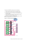
The following sections describe how to prepare these tape libraries in more
detail.
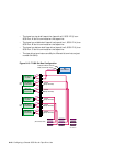
8.10.1 Communications with the Host Computer
Two types of communications are possible between the tape library and
the host computer: SCSI and EIA/TIA-574 serial (RS-232 for nine-pin
connectors). Either method, when used with the multi-unit controller
(MUC), allows a single host computer to control up to five units.
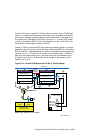
A TruCluster Server cluster supports SCSI communications only between
the host computer and the MUC. With SCSI communications, both control
signals and data flow between the host computer and tape library use the
same SCSI cable. The SCSI cable is part of the shared SCSI bus.
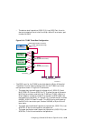
An RS-232 loopback cable must be connected between the Unit 0 and Input
nine-pin connectors on the rear connector panel. The loopback cable connects
the MUC to the robotic controller electronics.
Switch 7 on the MUC switch pack must be down to select the SCSI bus.
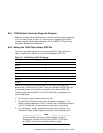
8.10.2 MUC Switch Functions
Switch pack 1 on the rear of the multi-unit controller (MUC) is located
below the MUC SCSI connectors. The switches provide the functions shown
in Table 8–6.
8–42 Configuring a Shared SCSI Bus for Tape Drive Use