


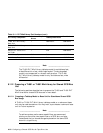
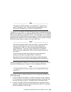
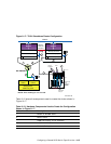
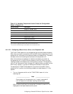

Figure 8–17: TL891 Standalone Cluster Configuration
KZPBA-CB (ID 7)
Memory
Channel
Interface
Memory Channel
KZPBA-CB (ID 6)
Memory Channel
Member
System
2
Member
System
1
DS-DWZZH-03
T
T
T
2
1
4
1
3
StorageWorks
RAID Array 7000
HSZ70HSZ70
Controller B Controller A
T
KZPBA-CB (ID 7)
5 5
6
7
KZPBA-CB (ID 6)
T
T
Network
T
NOTE: This drawing is not to scale.
Library
Robotics
Expansion
Unit
Interface
DLT1
TL891
DLT2
0.3 m
SCSI Bus
Jumper
6
7
ZK-1627U-AI
Table 8–12 shows the components used to create the cluster shown in
Figure 8–17.
Table 8–12: Hardware Components Used to Create the Configuration
Shown in Figure 8–17
Callout Number
Description
1
BN38C or BN38D cable
a
2
BN37A cable
b
3
H8861-AA VHDCI trilink connector
4
H8863-AA VHDCI terminator
5
BN21W-0B Y cable
Configuring a Shared SCSI Bus for Tape Drive Use 8–57