


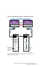
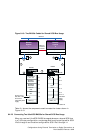
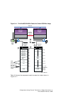
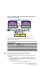
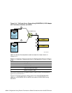
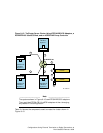


Figure 9–13: Externally Terminated Shared SCSI Bus with HSZ50 RAID
Array Controllers at Bus End
KZPSA-BB (ID 7)
Network
Memory
Channel
Interface
Memory Channel
KZPSA-BB (ID 6)
Memory Channel
Member
System
2
Member
System
1
2
1
1
2
T
T
3
4
3
3
4
HSZ50
Controller A Controller B
HSZ50
ZK-1597U-AI
Table 9–3 shows the components used to create the cluster shown in
Figure 9–12 and Figure 9–13.
Table 9–3: Hardware Components Used for Configuration Shown in Figure
8–12 and Figure 8–13
Callout Number
Description
1
BN21W-0B Y cable
2
H879-AA terminator
3
BN21K (or BN21L) cable
ab
4
H885-AA trilink connector
a
The maximum combined length of the BN21K (or BN21L) cables must not exceed 25 meters.
b
The cable between the H885-AA trilink connectors on the HSZ50s could be a BN21L-0B, a 0.15-meter cable.
9.4.3.2 Cabling an HSZ20 in a Cluster using External Termination
To connect a SWXRA-Z1 (HSZ20 controller) to a shared SCSI bus, follow
these steps:
1. Referring to the RAID Array 310 Deskside Subsystem (SWXRA-ZX)
Hardware User’s Guide, open the SWXRA-Z1 cabinet, locate the SCSI
bus converter board, and:
• Remove the five differential terminator resistor SIPs.
Configurations Using External Termination or Radial Connections to
Non-UltraSCSI Devices 9–27