


Chapter 5 Trial Run and Tuning Procedure|ASDA-B Series
Revision January 2009 5-9
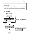
5.4 Speed Trial Run without Load
Before speed trial run, fix and secure the motor as possible to avoid the danger from the reacting
force when motor speed changes.
STEP 1:
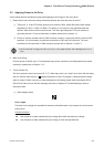
Set the value of parameter P1-01 to 4 and it is speed (Sz) control mode. Please ensure to set P1-01 when
the servo drive is Off (Servo Off). After selecting the operation mode as speed (Sz) control mode, please
restart the drive as P1-01 is effective only after the servo drive is restarted (after switching power off and on).
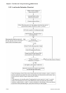
STEP 2:
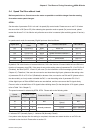
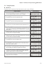
In speed control mode, the necessary Digital Inputs are listed as follows:
Digital Input
Parameter Setting
Value
Sign Function Description CN1 PIN No.
DI1 P2-10=101 SON Servo On DI1-=17
DI2 P2-11=109 TRQLM Torque limit enabled DI2-=18
DI3 P2-12=114 SPD0 Speed command selection 0 DI3-=5
DI4 P2-13=115 SPD1 Speed command selection 1 DI4-=3
DI5 P2-14=102 ARST Alarm Reset DI5-=15
DI6 P2-15=0 Disabled This DI function is disabled DI6-=14
By default, DI4 is the function of reverse inhibit limit, DI5 is the function of forward inhibit limit and DI6 is the
function of emergency stop (DI6), if the users do not set the setting value of parameters P2-13 to P2-15 to 0
(Disabled), the faults (ALE13, 14 and 15) will occur (For the information of fault messages, please refer to
Chapter 10). Therefore, if the users do not need to use these three digit inputs, please set the setting value
of parameters P2-13 to P2-15 to 0 (Disabled) in advance. Now, we need to use DI4 and D5 (please refer to
the above table), so it only needs to disable the DI6, i.e. set the setting value of parameter P2-15 to 0.
All the digital inputs of Delta ASDA-B series are user-defined, and the user can set the DI signals freely.
Ensure to refer to the definitions of DI signals before defining them (For the description of DI signals, please
refer to Table 7.A in Chapter 7).
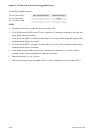
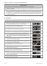
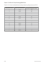
The speed command is selected by SPD0, SPD1. Please refer to the following table:
DI signal of CN1
Speed
Command No.
SPD1 SPD0
Command Source Content Range
S1 0 0 N/A
Speed command is
0(zero)
N/A
S2 0 1 P1-09 -5000 ~ 5000rpm
S3 1 0 P1-10 -5000 ~ 5000rpm
S4 1 1
Internal parameter
P1-11 -5000 ~ 5000rpm
0: indicates OFF (Normally Open); 1: indicates ON (Normally Closed)
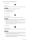
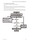
If any alarm code displays after the setting is completed, the users can restart the drive or set DI5 to be
activated to clear the fault. Please refer to section 5.2.