


Chapter 6 Control Modes of Operation|ASDA-B Series
6-6 Revision January, 2009
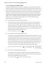
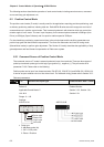
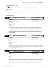
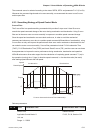
Electronic Gear Ratio Corresponding travel distance per pulse
When the electronic
gear ratio is not used
=
1
1
=
3x1000
4x2500
=
3000
10000
m
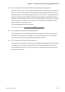
When the electronic
gear ratio is not used
=
10000
3000
=1 m
Table 6.B
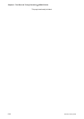
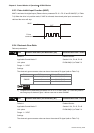
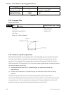
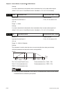
6.2.5 Low-pass Filter
Relevant parameters:
P1 - 08
PFLT
Smooth Constant of Position Command (Low-
pass Filter)
Communication Addr.: 0108H
Default: 0 Related Section:
Applicable Control Mode: P Section 6.2.5
Unit: 10ms
Range: 0 ~ 1000 (0: Disabled)
PFL
T
Target position
Position
Time (ms)
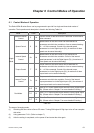
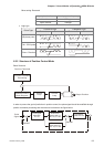
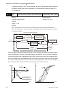
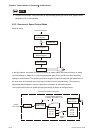
6.2.6 Position Loop Gain Adjustment
Before performing position control (setting position control block diagram), the users should complete
the speed control setting by using Manual mode (parameter P-32) since the position loop contains
speed loop. Then, adjust the Proportional Position Loop Gain, KPP (parameter P2-00) and Position
Feed Forward Gain, PFG (parameter P2-02). Or use Auto mode to adjust the gain of speed and position
control block diagram automatically.
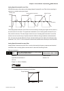
1) Proportional Position Loop Gain: To increase this gain can enhance the position loop
responsiveness.
2) Position Feed Forward Gain: To increase this gain can reduce the position track error during
operation.
The position loop responsiveness cannot exceed the speed loop responsiveness, and it is
recommended that the speed loop responsiveness should be at least four times faster than the position
loop responsiveness. This also means that the setting value of Proportional Speed Loop Gain, KVP
should be at least four times faster than Proportional Position Loop Gain, KPP.