


Chapter 6 Control Modes of Operation|ASDA-B Series
6-10 Revision January, 2009
NOTE
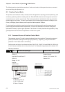
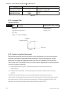
1) In speed control mode, if the users want to adjust analog speed input offset value, please refer to
parameter 4-22 for the operation.
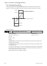
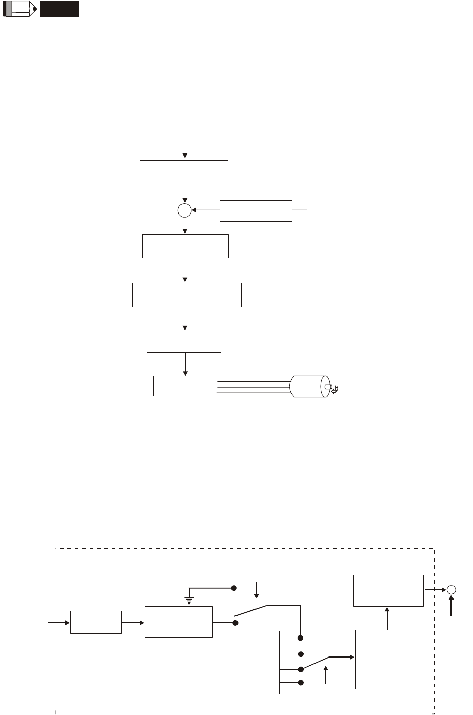
6.3.2 Structure of Speed Control Mode
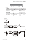
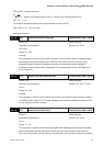
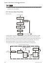
Basic Structure:
Speed Command
Speed Command
Processing
Torque Limiter
Current Loop
Speed Control
Block Diagram
Speed
Estimator
Resonant Suppression
Block Diagram
In the figure above, the speed command processing is used to select the command source of speed
control according to chapter 6.3.1, including proportional gain (P1-40) and S-curve filter smoothing
strategy of speed control. The speed control block diagram is used to manage the gain parameters of
the servo drive and calculate the current input provided to motor instantaneously. The resonance
suppression block diagram is used to suppress the resonance of mechanical system.
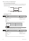
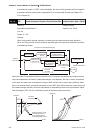
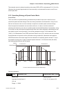
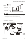
The function and structure of speed command processing is shown as the figure below:
Internal
Parameter
P1-09
1-10
P1-11
P
Low-pass
Filter P1-06
Analog
Command
S-curve
Filter
P1-34
P1-35
P1-36
SPD0,
SPD1
Proportional
Gain P1-40
A/D
Converter
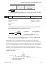
Control Mode Selection:
S mode / Sz mode P1-01
Speed Control Block Diagram