


Chapter 6 Control Modes of Operation|ASDA-B Series
6-26 Revision January, 2009
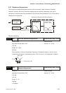
6.4.2 Structure of Torque Control Mode
Basic Structure:
Torque
command
Torque Command
Processing
Resonant Suppression
Block Diagram
Current Sensor
Current Control
Block Diagram
Output Torque
+
-
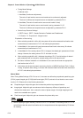
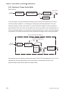
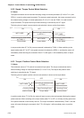
In the above figure, the toque command processing is used to select the command source of torque
control according to chapter 6.4.1, including max. analog torque command (parameter P1-41) and
smoothing strategy of torque control mode. The current control block diagram is used to manage the
gain parameters of the servo drive and calculate the current input provided to motor instantaneously. As
current control block diagram is too complicated, setting the parameters of current control block diagram
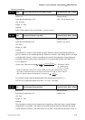
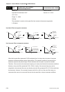
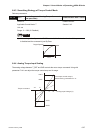
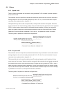
is not allowed. The function and structure of torque command processing is shown as the figure below:
Internal
Parameter
P1-12
1-13
P1-14
P
Low-pass
Filter P1-07
Analog
Command
TCM0,
TCM1
Proportional
Gain P1-41
A/D
Converter
Control Mode Selection:
T mode / Tz mode P1-01
Torque Control Block Diagram
The command source is selected according to the state of TCM0, TCM1 and parameter P1-01 (T or Tz).
Whenever the command signal needs to be more smoothly, we recommend the users to use
proportional gain (scalar) and low-pass filter to adjust torque.