


Chapter 7 Servo Parameters|ASDA-B Series
Revision January, 2009 7-47
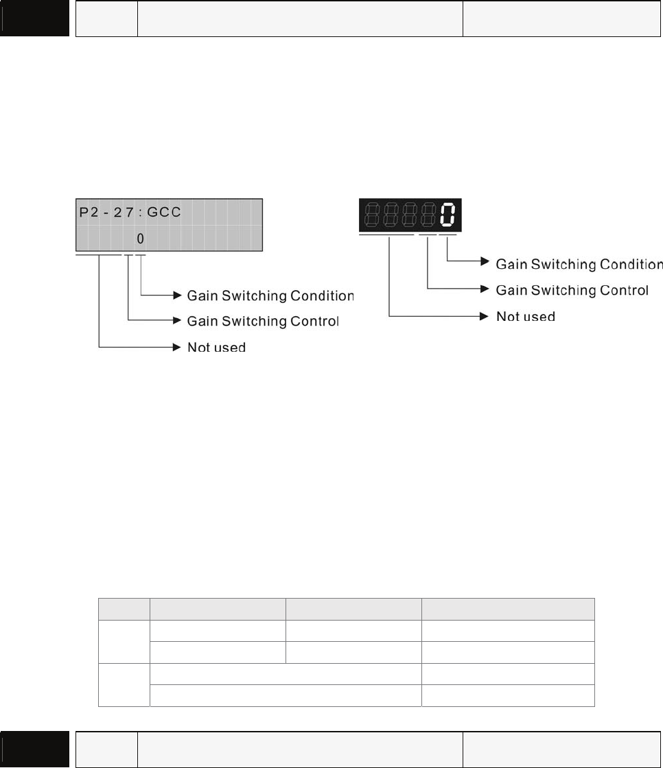
P2 - 27
GCC Gain Switching Control Selection Communication Addr.: 021BH
Default: 0 Related Section:
Applicable Control Mode: P/S P2-01, P2-05, P2-28, P2-29
Unit: N/A
Range: 0 ~ 14
Settings:
ASD-PU-01A ASD-PU-01B
• Gain Switching Condition Settings:
0: Disabled
1: Gain switching DI signal (GAINUP) is On. (see Table 7.A)
2: In position mode, position deviation is higher than the setting value of P2-29.
3: Position command frequency is higher than the setting value of P2-29.
4: Servo motor speed is higher than the setting value of P2-29.
• Gain Switching Control Settings:
0: Gain multiple switching
1: P Æ PI switching
Setting P mode P, S mode Status
P2-00 x 100% P2-04 x 100% Before switching
0
P2-00 x P2-01 P2-04 x P2-05 After switching
P2-06 x 0% Before switching
1
P2-06 x 100% After switching
P2 - 28
GUT Gain Switching Time Constant Communication Addr.: 021CH
Default: 10 Related Section:
Applicable Control Mode: P/S P2-27, P2-29
Unit: 10ms
Range: 0 ~ 1000
Settings:
0: Disabled
This parameter is used to set the time constant when switching the smooth gain.