


Chapter 3 Connections and Wiring|ASDA-B Series
3-18 Revision January 2009
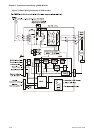
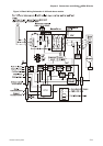
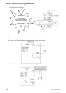
3.3.3 User-defined DI and DO signals
If the default DI and DO signals could not be able to fulfill the users’ requirements, there are still user-
defined DI and DO signals. The setting method is easy and they are all defined via parameters. The
user-defined DI and DO signals are defined via parameters P2-10 to P2-15 and P2-18 to P2-20.
Please refer to the following Table 3.G for the settings.
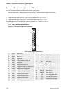
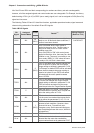
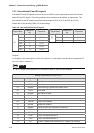
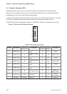
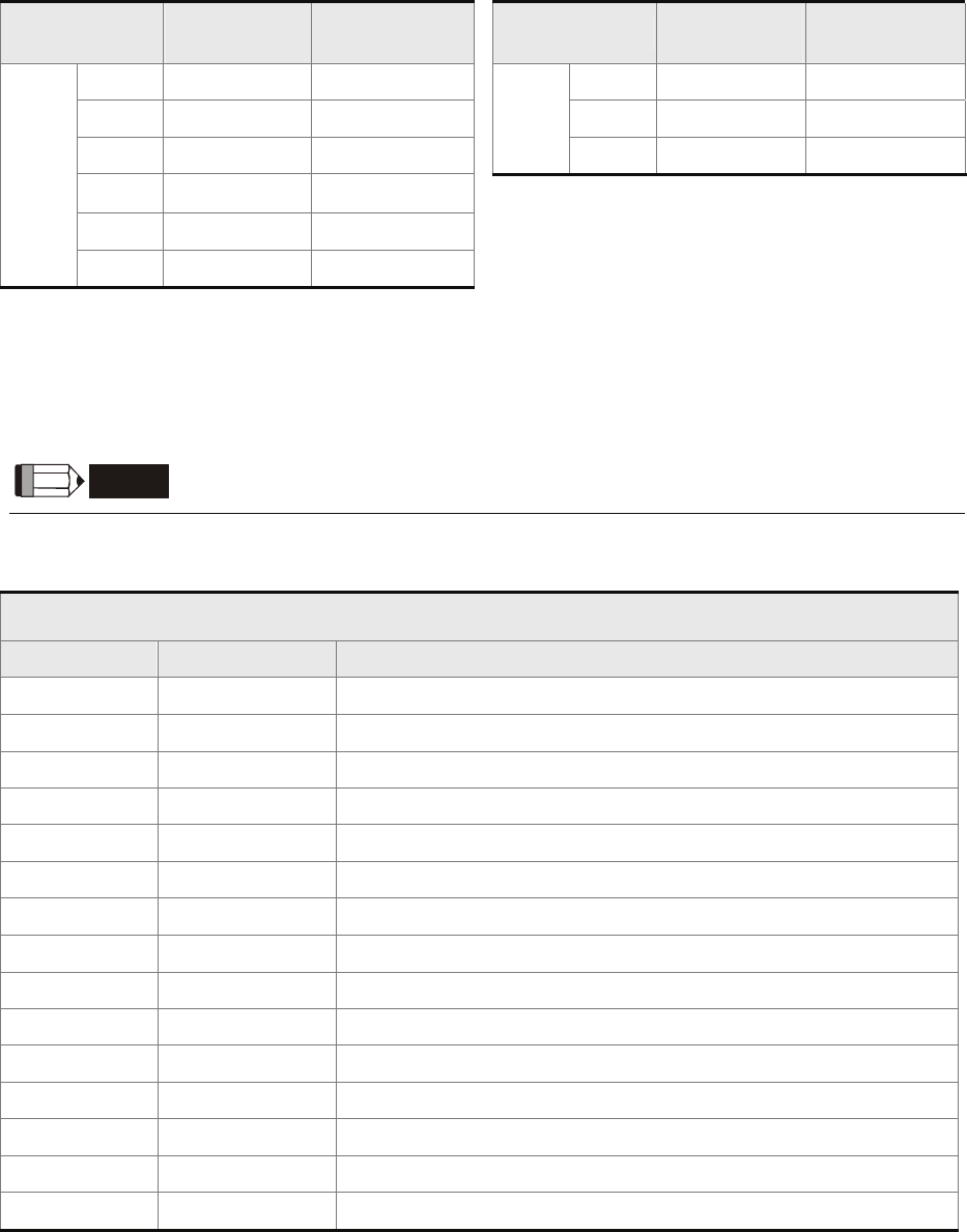
Table 3.G User-defined DI and DO signals
Signal Name
Default Pin
No.
Parameter Signal Name
Default Pin
No.
Parameter
DI1- 17 P2-10 DO1+ 16 P2-18
DI2- 18 P2-11 DO2+ 2 P2-19
DI3- 5 P2-12
DO
DO3+ 1 P2-20
DI4- 3 P2-13
DI5- 15 P2-14
DI
DI6- 14 P2-15
DI signal:
For example: If the users want to set DI1 to be servo on, it only needs to set the value of parameter P2-
10 to 101 (refer to chapter 7).
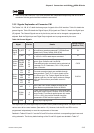
NOTE
1) 14~17: Single control mode;18~20: Dual control mode; 0: Input function disabled
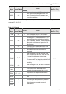
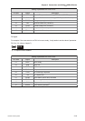
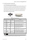
Setting of parameter P2-10 to P2-15:
DI Code Signal Description
01 SON Servo On
02 ARST Alarm Reset
03 GAINUP Gain switching in speed and position mode
04 CCLR Pulse clear
05 ZCLAMP Zero speed CLAMP
06 CMDINV Command input reverse control
07 INHP Pulse inhibit input
09 TRQLM Torque limit enabled
10 SPDLM Speed limit enabled
11 GNUM0 Electronic gear ratio (Numerator) selection 0
14 SPD0 Speed command selection 0
15 SPD1 Speed command selection 1
16 TCM0 Torque command selection 0
17 TCM1 Torque command selection 1
18 S-P Position / Speed mode switching (OFF: Speed, ON: Position)