


Chapter 3 Connections and Wiring|ASDA-B Series
Revision January 2009 3-15
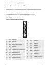
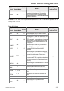
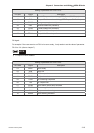
Pin No.
DO
Signal
Assigned
Control Mode
+
Details
(*1)
Wiring Diagram
(Refer to 3.3.3)
WARN ALL -
Servo warning output. WARN is activated
when the drive has detected Reverse limit
error, Forward limit error, Emergency stop,
Serial communication error, and Undervoltage
these fault conditions.
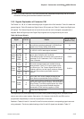
Footnote *1: The "state" of the output function may be turned ON or OFF as it will be dependant on the
settings of P2-10~P2-15.
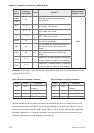
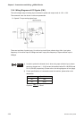
Table 3.C DI Signals
DI
Signal
Assigned
Control Mode
Pin No. Details
(*2)
Wiring Diagram
(Refer to 3.3.3)
SON
ALL 17 Servo On. Switch servo to "Servo Ready".
ARST
ALL 18
A number of Faults (Alarms) can be cleared by
activating ARST. Please see section 10.3 for
applicable faults that can be cleared with the
ARST command. However, please investigate
Fault or Alarm if it does not clear or the fault
description warrants closer inspection of the
drive system.
GAINUP
ALL - Gain switching in speed and position mode
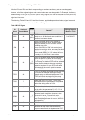
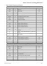
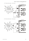
CCLR
P 5
When CCLR is activated the setting is
parameter P2-48 Pulse Clear Mode is
executed.
ZCLAMP
S , T -
When this signal is On and the motor speed
value is lower than the setting value of P1-38,
it is used to lock the motor in the instant
position while ZCLAMP is On.
The parameter P2-38 should be enabled first if
the users want to set the speed command that
has been accelerated and decelerated more
smoothly.
CMDINV
ALL -
When this signal is On, the motor is in reverse
rotation.
INHP
P -
Pulse inhibit input. When the drive is in
position mode, if INHP is activated, the
external pulse input command is not valid.
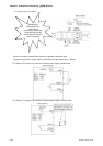
TRQLM
P , S , Sz -
ON indicates the torque limit command is
valid.
SPDLM
T , Tz -
ON indicates the speed limit command is
valid.
GNUM0
P - Electronic gear ratio (Numerator) selection 0
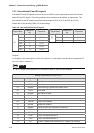
SPD0
SPD1
ALL -
Select the source of speed command:
See Table 3.D.
C8/C9