


Chapter 8 MODBUS Communications|ASDA-B Series
Revision January 2009 8-5
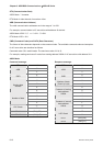
0302H
Communication
Protocol
Default: 0
Settings:
0: Modbus ASCII mode, <7,N,2>
1: Modbus ASCII mode, <7,E,1 >
2: Modbus ASCII mode, <7,O,1>
3: Modbus ASCII mode, <8,N,2 >
4: Modbus ASCII mode, <8,E,1>
5: Modbus ASCII mode, <8,O,1>
6: Modbus RTU mode, <8,N,2>
7: Modbus RTU mode, <8,E,1>
8: Modbus RTU mode, <8,O,1>
This parameter is used to set the communication protocol. The alphanumeric characters represent the
following: 7 or 8 is the number of data bits; N, E or O refer to the parity bit, Non, Even or Odd; the 1 or 2
is the numbers of stop bits.
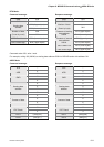
0303H
Transmission Fault
Treatment
Default: 0
Settings:
0: Display fault and continue operating
1: Display fault and stop operating
This parameter is used to determine the operating sequence once a communication fault has been
detected. If '1' is selected the drive will stop operating upon detection the communication fault. The
mode of stopping is set by parameter P1-32.
0304H
Communication Time
Out Detection
Watch Dog Timer (It is not recommended to change the factory default setting if
not necessary)
Default: 0
Range: 0 ~ 20 sec.
The factory default setting is set to 0 and it indicates this function is disabled.
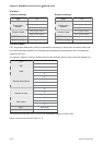
When this parameter is set to any value over 0, it indicates that the timer is enabled. The value set in
this parameter is the communication time and the communication time out detection should be
completed within the time. Otherwise, a communication error will occur. For example, if the value set in
this parameter is 5, it indicates that the communication time out detection will be activated once in five
seconds or a communication error will occur.
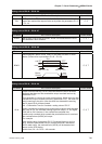
0306H
Digital Input
Communication
Function
Digital Input Contact Control:
Default: 0
Settings: 0 ~ 3F (hexadecimal number)
The setting of this parameter determines how the Digital Inputs (DI) accept commands and signals.
Input commands or signals through the DI can be either from an external source, through the CN 1
interface connector, or via communication, (RS-232, RS-485). If the Digital Input Contact Control
parameter for the DI 1 ~ 6 is set to "0", command is external, and via CN1; if it is set to "1" (decimal
number) the DI signal is via communication. Each of the six Digital Inputs are accessed individually and
can be set independently of each other. They can be programmed either via the drive's keypad or via