


190 © 2001- 2006 D-Link Corporation/D-Link Systems, Inc. All Rights Reserved.
D-Link Unified Access System User Manual
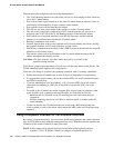
In Figure 83, WS1 and WS2 have a VLAN routing interface on the L3 Tunnel subnet. The
following commands show how to configure the interface for WS1, which has a VLAN
Routing interface with VLAN ID 200 and an IP address of 192.168.60.15.
1. Enter VLAN config mode, create a VLAN, and give it a name.
(switch-prompt) #vlan database
(switch-prompt) (Vlan)#vlan 200
(switch-prompt) (Vlan)#vlan name 200 "L3 Tunnel"
2. Create a VLAN routing interface on VLAN 200.
(switch-prompt) (Vlan)#vlan routing 200
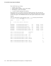
3. Exit to Privileged EXEC mode and view the VLAN routing interface configuration.
(switch-prompt) (Vlan)#exit
(switch-prompt) #show ip vlan
MAC Address used by Routing VLANs: 00:00:00:01:00:02
Logical
VLAN ID Interface IP Address Subnet Mask
------- -------------- --------------- ---------------
200 0/4/1 0.0.0.0 0.0.0.0
The new VLAN routing interface is 0/4/1 in unit/slot/port format. For non-stacking
platforms, the interface would be 4/1.
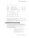
4. Enter the interface configuration mode for the new VLAN routing interface.
(switch-prompt) #configure
(switch-prompt) (Config)#interface 0/4/1
5. Assign an IP address to the interface and enable routing.
(switch-prompt) (Interface 0/4/1)#ip address 192.168.60.15 255.255.255.0
(switch-prompt) (Interface 0/4/1)#routing
6. Add the port to which the call server is attached to VLAN 200 (in this example, the call
server is attached to port 3).
(switch-prompt) (Config)#interface 1/0/3
(switch-prompt) (Interface 1/0/3)#vlan participation include 200
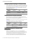
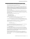
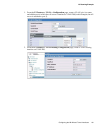
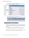
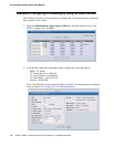
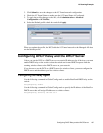
To perform the same steps by using the Web interface, use the following procedures: