


D-Link Unified Access System Topology 21
1 Overview of the D-Link Unified Access System
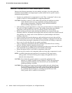
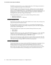
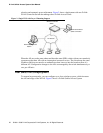
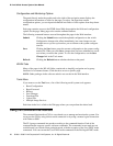
Figure 1 shows an example of a floor plan and network with a D-Link WLAN Controller
Switch that manages two APs. The graph also shows a peer switch and a rogue AP in the
network.
Figure 1. Sample WLAN Visualization
The WLAN Visualization tool provides an AP power display with color-coded channels to
help you determine where to physically place access points to reduce interference or increase
coverage on your WLAN.
D-Link Unified Access System Topology
The WLAN network topology you use depends on the size and requirements of your network.
Small-to-medium networks might require only one WCS that manages a few D-Link Access
Points. For larger networks that need greater roaming capabilities for wireless clients, a
deployment with multiple peer switches that each manage several APs might be appropriate.
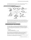
Single WCS Deployment
When you deploy a D-Link Access Point, the D-Link WLAN Controller Switch can
automatically detect the AP and assign a default profile, which includes automatic RF channel