


WLAN Topology Considerations 33
2 Planning the D-Link Unified Access System Network
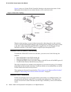
Since the D-Link WLAN Controller Switch has Layer 2/3 switching functions as well as
WLAN data and management functions, you can connect D-Link Access Points, wired PCs, or
other network equipment such as hubs, routers, or other switches directly to the 10/100 Mbps
Ethernet ports on the switch. All connections to the D-Link WLAN Controller Switch must be
wired connections since the switch does not have any radios.
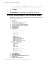
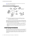
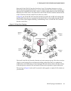
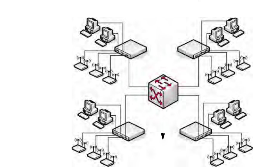
In Figure 8, the D-Link WLAN Controller Switches are both LAN and WLAN switches that
handle traffic from end users connected to the wired LAN as well as traffic from the D-Link
Access Points. In the diagram, Building 1 and Building 2 have a D-Link WLAN Controller
Switch on each floor.
Figure 8. Wiring Closet Topology
The four D-Link WLAN Controller Switches are in the same peer group. This allows wireless
clients to roam between floors and between buildings without the need to re-authenticate.
Additionally, each WCS shares its list of managed APs and wireless clients with the switches
in the peer group so that the APs and wireless clients are not reported as rogues (unknown).
The topology in Figure 8 works well if you need to add, upgrade, or replace LAN switches on
your network.
APs
WCS
WCS
WCS
WCS
APs
APs
APs
L2/L3 Distribution Switch
To Network
Backbone
Building 1
Floor 2
Building 1
Floor 1
Building 2
Floor 2
Building 2
Floor 1