


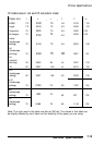
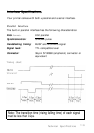
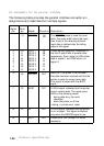
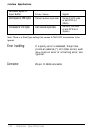

Pin assignments for the parallel interface
The following table provides the parallel interface connector pin
assignments and describes the interface signals.
Return
pin
Direction Description
IN
The STROBE pluse to read the input
data. The pulse width should be more
Signal
pin
Signal
19
STROBE
2
3
4
5
6
7
8
9
10
DATA 1
DATA 2
DATA 3
DATA 4
DATA 5
DATA 6
DATA 7
DATA 8
IN
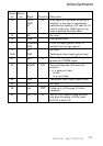
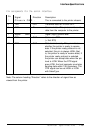
ACKNLG
than 0.5µs at the receiving terminal.
Input data is latched after the falling
edge of this signal.
These signals represent information in
the first to eighth bits of parallel data,
respectively. Each signal is HIGH when
data is logical 1 and LOW when it is
logical 0.
IN
IN
IN
IN
IN
IN
IN
OUT
20
21
22
23
24
25
26
27
28
About an 11µs pulse. LOW indicate:;
that data has been received and that the
printer IS ready to accept more data
This signal is paired with the BUSY
signal.
A HIGH signal indicates that the printer
cannot receive data. The signal goes
HIGH in the following cases:
•
during data en:ry (for each
character)
•
when the printer is off line
l during a printer-error state.
11
29
BUSY
OUT
Text
Text
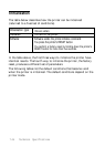
OUT
A HIGH signal indicates that the printer
is out of paper. The signal is effective
only when the ERROR signal is low.
PE
SLCT
30
OUT
Pulled up to +5V through 3.3 Kohm
resistance.
7-20
Technical Specifications