


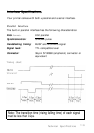
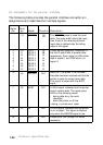
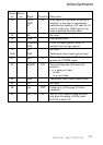
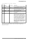

Interface Specifications
Signal Return
pin pin Signal
Direction Description
14 -
AUTO
IN
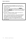
If this signal is LOW when the printer is
FEED
initialized, a line feed is automatically
XT
performed by inputting a CR code (in LO
and FX mode only). SelecType can be
used to produce the same effect.
15 - NC
-
Not used.
16 -
GND
-
Logic ground level.
17
CHASSIS
Printer's chassis ground, which is
GND
isolated from the logic ground.
18
NC
Not used.
19-30 -
GND
-
Twisted-pair return signal ground level.
31 -
INIT
IN
When this signal goes LOW, the printer
ignores the STROBE signal.
32 -
ERROR OUT
This level becomes LOW when the
printer is:
• in a paper-out state
•
off line
•
in an error state.
33 -
GND
-
Twisted-pair return signal ground level.
34 NC
-
Not used.
35 -
+5v
OUT
Pulled up to +5V through 3.3 Kohm
resistance.
36
SLCT IN IN
The DC1/DC3 control codes are valid
only when this signal is HIGH (when
SLCT IN is set to off).
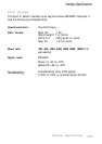
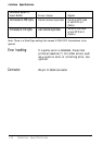
Technical Specifications
7-21