


ADVANCED OPERATIONS INSTRUCTIONS FOR BUILDING A GPI TRIGGER
121
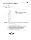
INSTRUCTIONS FOR BUILDING A GPI TRIGGER
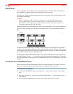
This section contains a diagram of the GPI Trigger Button you can build and all associated instruc-
tions.
Required Tools
and Parts
Soldering Iron and Solder
Wire Cutters
Electric Drill
Parts Required
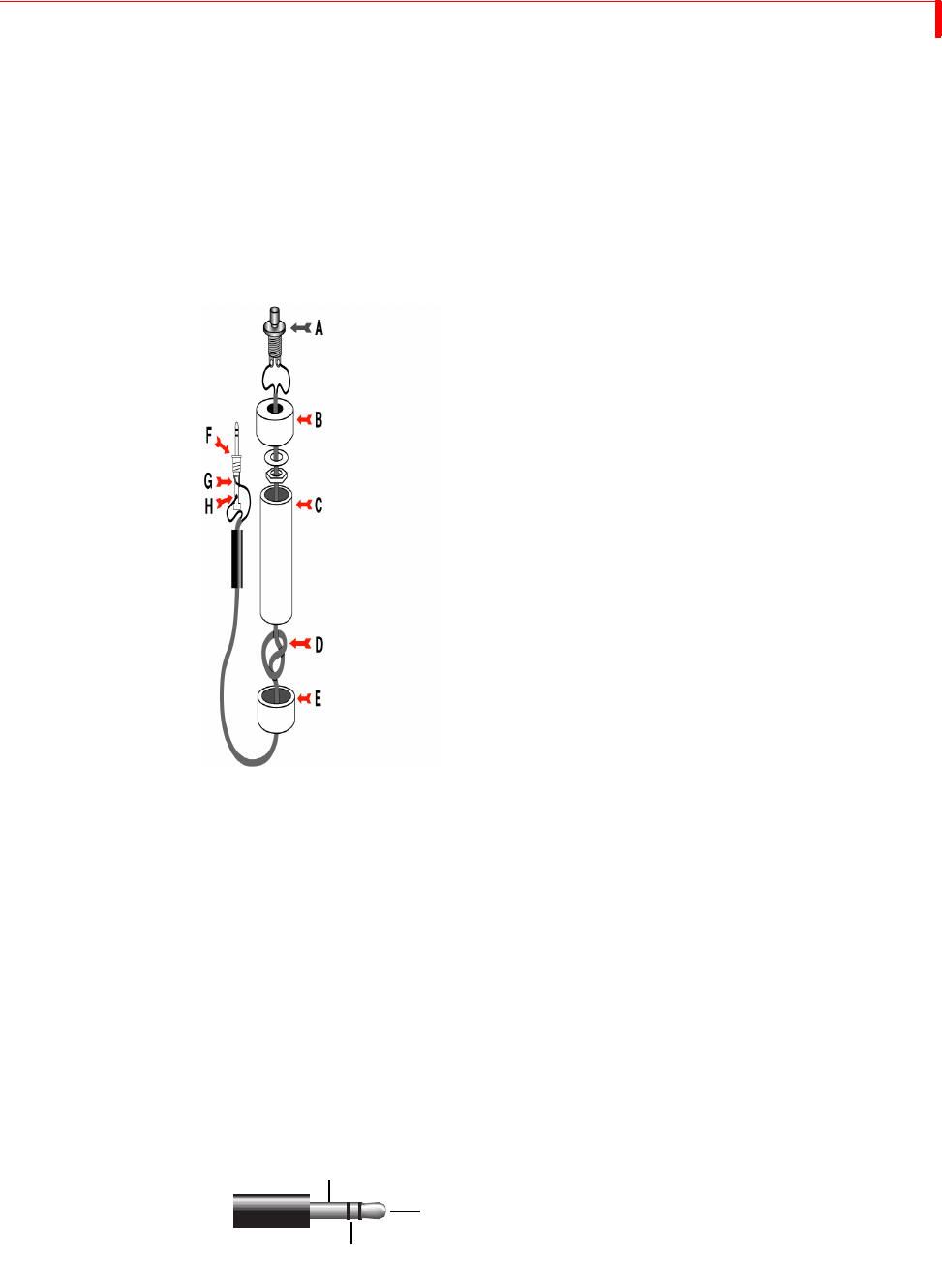
A “normally open momentary push-button switch” (A).
One four-inch piece of 3/4-inch PVC pipe (C) and two end caps
(B and E).
3-conductor, 22-24 gauge stranded wire cable (D).
A stereo 3.5-mm mini-pin plug (F)
Instructions 1 Drill a 1/4-inch hole in the center of one PVC end cap (E) and a hole to match the push-button
switch in the other end cap (B).
2 Feed one end of the cable through the end cap with the 1/4-inch hole (E) and strip the end of
each wire.
3 Tie a single knot (D) about 8 inches from the end of the wire.
4 Slide the wire through the PVC pipe, the nut and washer, and the other end cap (B).
5 Solder the two wires at the knotted end to the two poles on the switch (A).
6 Slip the switch into the end cap and secure it using the nut and washer.
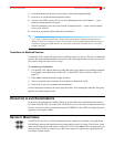
7 Solder the other ends of the cable to the plug (F).
8 Connect to the tip (G) and the base (H) of the plug. Don’t connect anything to the middle sec-
tion of the plug.
9 Push the end caps in place.
10 After you’ve tested the unit, you can cement the end caps (A and E) into place, if you want.
Tip
Base
Middle Section