


MX-4 DV USER GUIDE CHAPTER 3
24
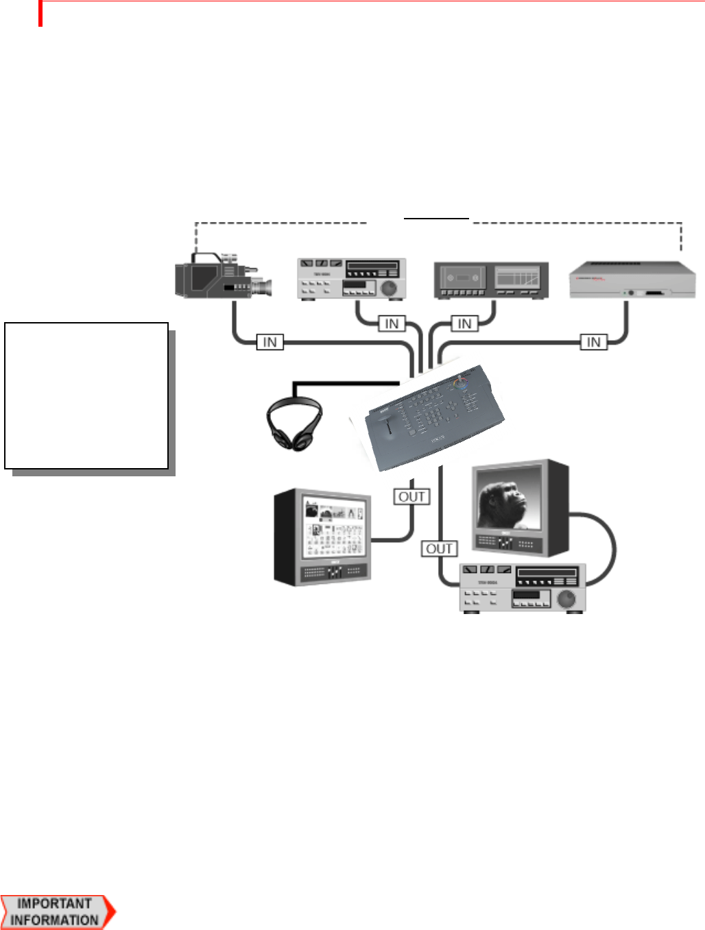
INSTALLATION EXAMPLES
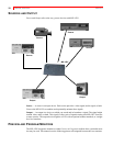
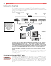
This section shows examples of two common MX-4 DV configurations, but does not describe
every possibility. Before proceeding, study the following diagram (MX-4 DV Installation Concept)
that shows overall configuration concepts.
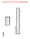
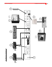
MX-4 DV Installation Concept
You can have up to four separate audio/video input sources active at any given time. The MX-4
DV designates them as sources A, B, C, and D. You can use any mix of devices as necessary to
complete your work so long as they are valid MX-4 DV devices. For example, you can use VCRs,
VTR’s, camcorders, laserdisc players, satellite tuners, broadcast tuners/receivers, character genera-
tors (CG’s), video-equipped computers, and audio devices (such as a CD player or tape deck).
The MX-4 DV sends the output signal to a recording device (such as a VCR) and/or a Program
monitor.
Use a second monitor, Preview, to display preview images of all input sources. The Preview moni-
tor also displays the on-screen controls you use to operate MX-4 DV. The Preview monitor is
required for operation.
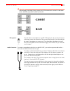
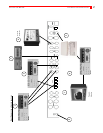
Correlating Input Sources to MX-4 DV Jacks
As stated above, the MX-4 DV designates your input sources as A, B, C, and D. However, if you
examine the jacks on the MX-4 DV rear panel, you’ll see they are labeled 1, 2, 3, and 4. Initially,
there is a direct correlation between the letter and the number designations: jack 1 corresponds to
source A, jack 2 corresponds to source B, jack 3 corresponds to source C, and jack 4 to source D.
You can re-route inputs to other channels. For more information, refer to “Route” beginning on
page 73.
SOURCES
Channel
A
Channel
B
Channel
C
Channel
D
Preview
Output
Program
Headphones
This diagram illustrates
the overall concept for
installing equipment with
MX-4 DV. Please study it
before you begin
installing your own
equipment.