


3–2 MULTILINK ML1600 ETHERNET COMMUNICATIONS SWITCH – INSTRUCTION MANUAL
CONNECTING ETHERNET MEDIA CHAPTER 3: INSTALLATION
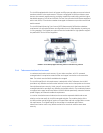
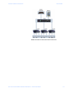
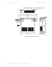
3.2 Connecting Ethernet Media
3.2.1 Description
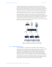
The ML1600 switches are specifically designed to support standard Ethernet media types
within a single unit. This is accomplished by using a family of modules that are individually
selected and configured. Refer to Communications Modules on page 2–3 for details on
these modules.
The supported media types with the corresponding IEEE 802.3, 802.3D, 802.3u, 802.3AB
and 802.3z standards and connector types are as follows:
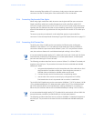
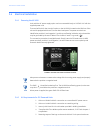
3.2.2 Connecting ST-type Fiber Optics (twist-lock)
The following procedure applies to installations using modules with ST-type fiber
connectors. These are type A1, A2, A4, A5, A6, and A7 modules.
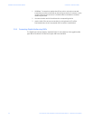
1. Before connecting the fiber optic cable, remove the protective dust caps from
the tips of the connectors on the module. Save these dust caps for future use.
2. Wipe clean the ends of the dual connectors with a soft cloth or lint-free lens
tissue dampened in alcohol. Ensure the connectors are clean before
proceeding.
Note
One strand of the duplex fiber optic cable is coded using color bands at regular intervals.
The color-coded strand must be used on the associated ports at each end of the fiber optic
segment.
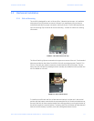
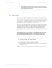
3. Connect the transmit (TX) port on the module (light colored post) to the receive
(RX) port of the remote device. Begin with the color-coded strand of the cable
for this first TX-to-RX connection.
4. Connect the receive (RX) port on the module (dark colored post) to the transmit
(TX) port of the remote device. Use the non-color coded fiber strand.
5. The LINK LED on the module will illuminate when a connection has been
established at both ends (assuming power is ON). If LINK is not lit after cable
connection, the cause may be improper cable polarity. Swap the fiber cables
at the module connector to remedy this situation.
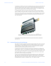
3.2.3 Connecting SC-type Fiber Optics (snap-in)
The following procedure applies to installations using modules with SC-type fiber
connectors. These include the A3, A8, A9, G3, G4, and G5 modules.
Table 3–1: Ethernet media
IEEE standard Media type Distance
100Base-FX multi-mode fiber 220 m
single-mode fiber 5 km
10Base-T twisted-pair 100 m
100Base-TX 100Base-FX 100 m