


3–6 MULTILINK ML1600 ETHERNET COMMUNICATIONS SWITCH – INSTRUCTION MANUAL
MECHANICAL INSTALLATION CHAPTER 3: INSTALLATION
To release the ML1600 from the DIN-rail, simultaneously press down the top of the DIN-rail
latches to release the switch, which can then be dismounted by pulling the bottom out.
Once the bottom of the ML1600 is rotated out, the DIN-rail latch is not engaged and the
switch can be moved up and out, free of the DIN-rail mounting.
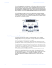
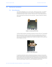
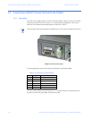
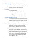
The following figure shows the vertical mounting of the ML1600 on a DIN-rail track for
proper convection cooling. Note there is air space in the rear, as the ML1600 is held out
from the rear of the panel by the mounting brackets. The ML1600 design uses the case for
cooling (patent pending) and needs to be mounted vertically with air flow space in the
front, rear, and sides.
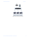
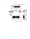
FIGURE 3–3: ML1600 mounted vertically with DIN-rail brackets and latches
The DIN-Rail mounting brackets and latches are optional and need to be ordered as
separate items.
3.3.2 Mounting Dimensions with Metal Brackets
Each MultiLink ML1600 is supplied with metal mounting brackets and screws to mount the
unit securely. It is recommended to mount the ML1600 vertically for proper cooling and
long-life reliability. It is also advisable to mount the unit with space for air movement
around the top and the sides, typically a minimum of 1 inch.
The back of the ML1600 unit is held out from the panel or wall behind it, creating a rear
space of about ¼ inch or 1 cm. This allows air circulation and cooling of the rear part of the
case. Since the ML1600 uses special internal thermal techniques (patent pending) to move
the heat generated by the electronic components inside into the case, the case may be
quite warm to the touch during normal operation.
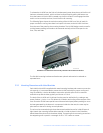
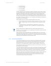
The unit can be mounted using the brackets turned outside (normal) or inside (if space is
tight). Attach the mounting bracket either outside or inside as shown in the illustration
below (dotted line shown for the brackets inside). The spacing for the mounting screws into
the supporting wall or panel is a rectangle 11.89" × 7.85" center-to-center.
754710A1.CDR