


3–8 MULTILINK ML1600 ETHERNET COMMUNICATIONS SWITCH – INSTRUCTION MANUAL
ELECTRICAL INSTALLATION CHAPTER 3: INSTALLATION
3.4 Electrical Installation
3.4.1 Powering the ML1600
Units with the AC power supply option can be connected directly to 110/240 V AC with the
supplied power cord.
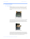
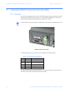
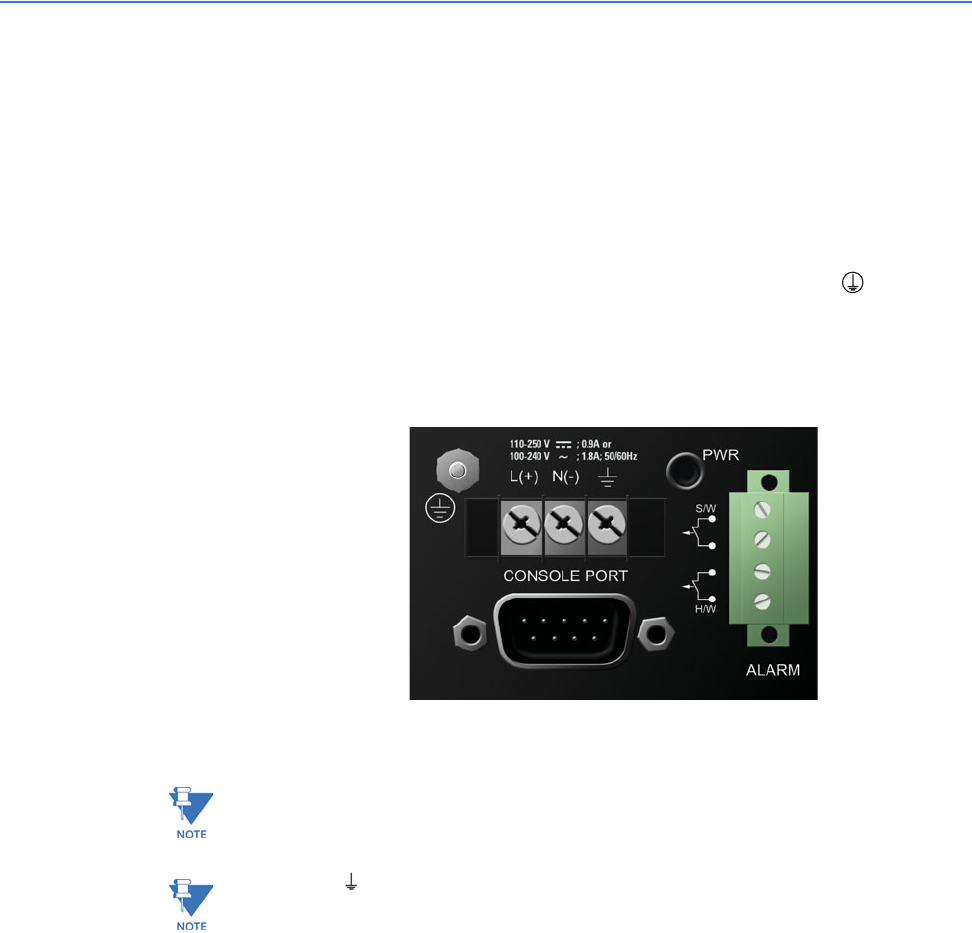
The terminal block for the HI and LO option on the ML1600 is located on the left front of the
unit and is equipped with three (3) screw-down lead posts. The power terminals are
identified as positive (+) and negative (–), and they are floating inside the unit so that either
may be grounded by the user if desired. The chassis is “earth” or ground ( ).
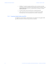
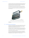
The connection procedure is straightforward. Simply insert the DC leads to the ML1600
power terminals, positive (+) and negative (-) screws. Please ensure correct polarity and
that each lead is securely tightened.
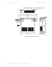
FIGURE 3–5: Power connection and alarm contacts
Note
Always use a voltmeter to measure the voltage of the incoming power supply and properly
determine the positive or negative leads.
Note
The GND ( ) should be hooked up first. The ML1600 has a floating ground, so the user
may elect to ground either the positive or negative terminal.
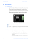
When power is applied, the green PWR LED will illuminate.
3.4.2 UL Requirements for DC-Powered Units
1. Minimum 18 AWG cable for connection to a centralized DC power source.
2. Minimum 14 AWG cable for connection to a earthing wiring.
3. Use only with listed 10 A circuit breaker provided in building installation.
4. “Complies with FDA radiation performance standards, 21 CFR sub-chapter J”
or equivalent.
5. Fastening torque of the lugs on the terminal block: 9 inch-pound maximum.