


CHAPTER 3: INSTALLATION MECHANICAL INSTALLATION
MULTILINK ML1600 ETHERNET COMMUNICATIONS SWITCH – INSTRUCTION MANUAL 3–5
3.3 Mechanical Installation
3.3.1 DIN-rail Mounting
The ML1600 is designed for use in a “factory floor” industrial environment. It is available
with optional DIN-rail brackets to mount it securely in a metal factory floor enclosure,
maintained vertically for proper convection cooling of the unit. The ML1600 requires two
DIN-rail mounting clips or latches for secure mounting – contact GE Multilin for ordering
information.
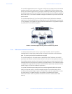
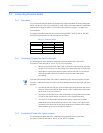
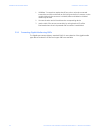
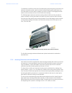
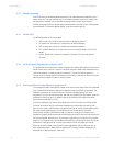
FIGURE 3–1: ML1600 with DIN-rail clips
The DIN rail latching clips are mounted on the upper rear corners of the unit. Two threaded
holes are provided on the sides of ML1600 for DIN-rail mounting purposes. Two #10-32 ×
3/8 PHIL. PAN with star washer screws are included with the DIN-rail brackets. The two
heavy duty DIN-rail latches are designed to be manually accessible from the top when the
unit is installed on a DIN-rail.
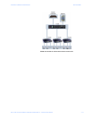
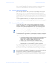
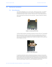
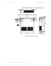
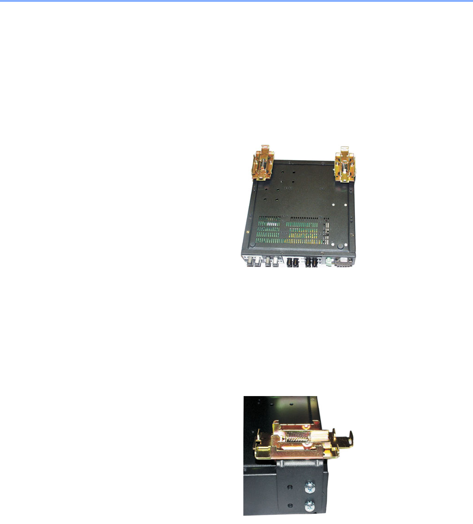
FIGURE 3–2: DIN-rail latch (detail)
To install the ML1600 with the DIN-rail brackets and latches, hold the unit in the vertical
position with the bottom out and with the top toward the DIN-rail. Position the latches over
the top of the DIN-rail, then snap the latches into holding position by moving the bottom of
the switch inwards to a vertical position. The heavy-duty DIN-rail latches and brackets will
hold the ML1600 securely in position, even with cabling attached to the unit.
754708A1.CDR
754709A1.CDR