


DC controller PCA and tray
Before proceeding, remove the following components:
●
Upper-left cover. See
Upper-left cover on page 96.
●
Power-supply cover. See
Power-supply cover on page 98.
●
Front-top cover. See
Front-top cover on page 100.
●
Rear-top cover. See
Rear-top cover on page 102.
●
Rear cover. See
Rear cover on page 112.
●
Interconnect board (ICB). See
Interconnect board (ICB) on page 153.
●
Low-voltage power supply. See
Low-voltage power supply (LVPS) on page 157.
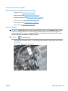
Remove the DC controller PCA and tray
CAUTION: ESD-sensitive part.
NOTE: To locate DC controller connector locations, see DC controller connector locations
on page 281.
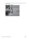
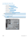
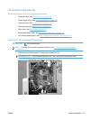
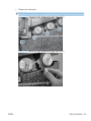
1. Disconnect all the connectors. There are 32 connectors in all.
Reinstallation tip The connector locations J101, J102, J106, and J154 are not used.
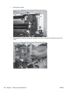
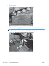
Figure 2-137 Remove the DC controller PCA and tray (1 of 3)
ENWW Internal assemblies 161